Product Overview
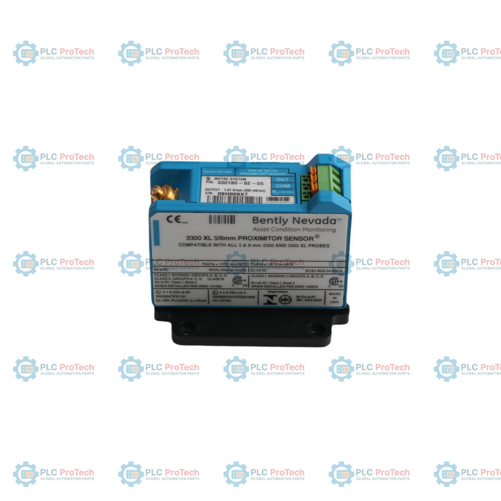
The 330180-92-05 is a high-precision, eddy-current displacement conditioning device developed by Bently Nevada for the 3300 XL Machinery Health Monitoring series. Acting as the core signal processing module within a non-contacting proximity probe circuit, this hardware converts raw radio-frequency (RF) field variations into linear voltage metrics directly proportional to shaft position. Mission-critical industrial assets—including large-scale steam turbine generators in power plants, high-pressure centrifugal compressors in oil refineries, and heavy-duty grinding mills in mining processing sites—rely on the 330180-92-05 (330180-92-05) to track dynamic fluid-film bearing clearance. By delivering stable, sub-micron vibration and thrust readings directly to a 3500 rack system, this sensor detects structural oil whip or shaft misalignment early. This eliminates unexpected catastrophic machine trips, protects high-cost rotating shafts, and reduces factory unprogrammed downtime.
Suffix Breakdown
The exact hardware configuration, total system loop calibration, and hazardous location approval profile of the 330180-92-05 proximity sensor can be systematically decoded through its alphanumeric suffix structure.
-
330180 Product Root: Identifies the fundamental hardware classification for the high-performance 3300 XL Proximitor Sensor unit.
-
-92 System Length Option: Dictates a total calibrated loop system length of 9.0 meters (29.5 feet). This parameter ensures the internal oscillator matches the impedance of a 9.0-meter combined probe and extension cable kit without requiring local field recalibration. This option specifically specifies a panel-mount chassis with no specialized DIN-rail mounting hardware included.
-
-05 Multi-Agency Approval Option: Certifies that the module meets strict international hazardous area explosion-proof standards, carrying full, simultaneous CSA, ATEX, and IECEx safety certifications for installation in Zone 0, Zone 1, and Zone 2 explosive environments.
Technical Performance Standards & Dimensions
| Machinery Protection Parameter |
Industrial Sensor Engineering Value |
| Model Identity |
330180-92-05 |
| Brand Manufacturer |
Bently Nevada (Baker Hughes Business Unit) |
| Control System Line |
3300 XL Proximity Transducer Platform |
| Transducer Interfacing |
Accepts 3300-series 5 mm, 3300 8 mm, and 3300 XL 8 mm Probes |
| Chassis Structural Material |
Premium Grade A308 Cast Aluminum Shell |
| System Scale Calibration |
9.0 meters (Total shared probe and cable length) |
| Signal Scale Factor |
7.87 V/mm (200 mV/mil) Nominal Linear Output |
| Operating Current Draw |
2 mA to 12 mA Nominal Current Consumption |
| Nominal Supply Voltage |
-24 VDC Negative Supply Input via Monitor Rack |
| Net Hardware Weight |
0.246 kg |
| Operating Thermal Window |
-51 to +100 deg C Extended Ambient Range |
| Storage Temperature Bounds |
-51 to +105 deg C Structural Storage Envelope |
| Manufacturing Location |
United States (USA) |
Transducer Maintenance & Operational FAQs
Can this 9.0-meter Proximitor sensor operate with a standard 5.0-meter extension cable assembly?
No. The internal oscillation matrix of the 330180-92-05 is specifically tuned to match the capacitive and inductive characteristics of a 9.0-meter system. Mixing this module with a 5.0-meter probe and cable kit shifts the resonant frequency, which alters the scale factor from the standard 7.87 V/mm (200 mV/mil) and results in incorrect vibration data.
What specific field benefits does the A308 cast aluminum enclosure material provide?
The premium A308 cast aluminum housing acts as a durable shield that blocks high-frequency electromagnetic interference (EMI) and radio-frequency noise from affecting the internal circuitry. It also provides excellent physical protection against mechanical impacts, atmospheric corrosion, and moisture ingress in harsh compressor deck environments.
How does an electrical technician identify a probe short-circuit versus an open-circuit fault during runtime?
By measuring the DC gap voltage at the sensor terminal block, field technicians can quickly check system integrity. A reading of 0 VDC or a very low positive value indicates a short-circuit condition, typically caused by a crimped cable trace or a grounded terminal connection. Conversely, a reading that matches the full supply voltage (-24 VDC) indicates an open-circuit fault, pointing to a broken terminal line or a severed probe tip.
Engineering & Installation Guide
-
Coaxial Connector Insulation and Structural Moisture Guarding:
When joining the probe lead to the extension cable inside the machine bracket, the coaxial connection must be completely isolated from the machine frame using high-dielectric silicone sleeves. Moisture or dirt inside this connection can degrade the RF signal, causing immediate measurement drift. Wrap the completed junction in self-fusing vulcanizing tape to keep out moisture on open compressor decks.
-
Gap Voltage Alignment and Calibration Benchmarks:
During installation, set the physical probe gap using a digital multimeter connected across the sensor's "OUT" and "COM" terminal terminals. Rotate the probe body until the DC voltage measures exactly -10.0 VDC, which corresponds to the precise mid-point center of the sensor's linear calibration range. Tighten the probe locknut to the recommended installation torque specification to prevent mechanical drift during high-vibration turbine operations.
-
Terminal Board Wiring Layout and Noise Isolation Protocols:
Route the -24 VDC power and signal output loops through high-integrity twisted, shielded instrumentation cables. Ground the cable shields at a single point only, typically at the 3500 monitor rack terminal block, and cut the field shield clean at the sensor end. This grounding technique prevents ground-loop current paths from introducing electrical noise into the vibration monitoring channels.