


Electromagnetic Induction in Industrial Coils
Understand how industrial coils create magnetic force, induce voltage, generate switching transients, and fail in relays, solenoids, transformers, motors, and proximity sensors. in service.
Manufacturer: Bently Nevada
Product No.: 330186-02
Country of origin:United States
Product Type: Proximity Probe Calibrators
Payment: T/T, Western Union
Weight: 320g
Shipping port: Xiamen
Warranty: 12 months
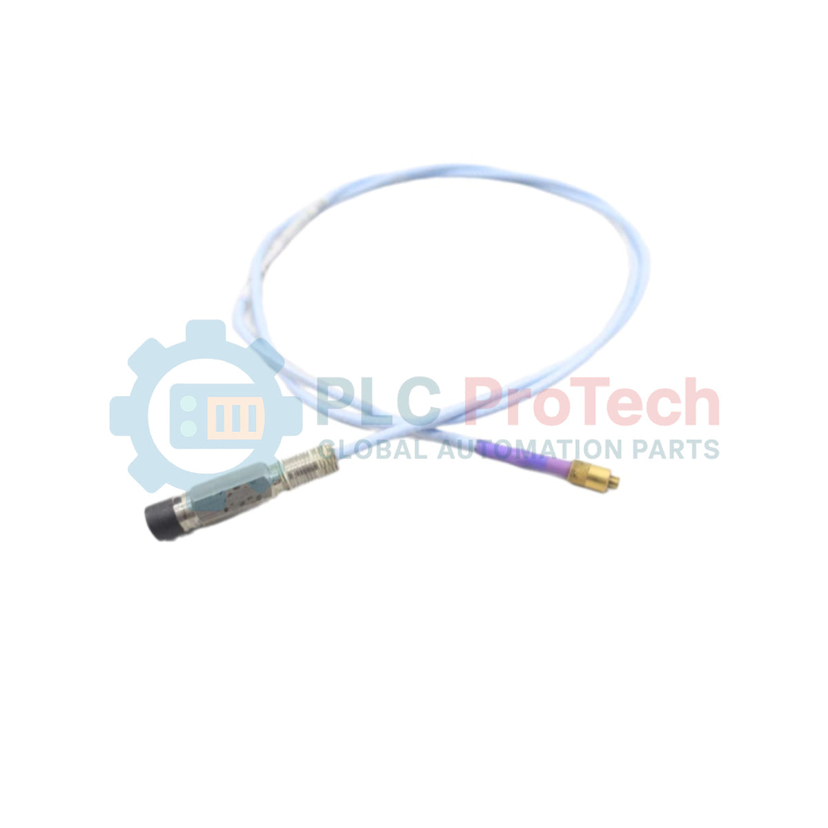
Optimizing proximity probe calibration and verification in the field, the Bently Nevada 330186-02 serves as a high-precision shaft micrometer within the 3300 XL series family. This precision mechanical instrument enables technicians to physically adjust and measure the gap between a proximity probe tip and a target button to verify the transducer system's voltage-to-gap calibration curve. Outfitted with a high-accuracy metric spindle, this calibration kit ensures that machinery protection systems are matched to exact physical clearances before commissioning.
| Parameter | Specification Value |
|---|---|
| Manufacturer | Bently Nevada |
| Part Number / SKU | 330186-02 |
| Series | 3300 XL |
| Scale Units | Metric micrometer units (0 to 25 mm) |
| Spindle Resolution | 0.01 mm |
| Target Material (Standard) | AISI 4140 steel (unless customized) |
| Probe Size Compatibility | Standard 5 mm and 8 mm proximity probes |
| Net Weight | 2.8 kg (6.2 lbs) |
| Shipping Weight (Calculated) | 4.0 kg (8.8 lbs) |
While the 330186-02 features a metric configuration (0-25 mm), English-scale variants (330186-01, calibrated in mils) are deployed where plant standards dictate imperial measurements. This spindle assembly can be used to calibrate legacy 3300 series proximity probes alongside 3300 XL series equivalents, provided correct adapter sleeves are utilized.
Always ensure that the target button attached to the micrometer face matches the metallurgical compound of the target shaft under monitoring. Standard systems assume AISI 4140 steel. Calibrating a proximity system configured for 4140 steel against an incorrect target material block will distort the average scale factor (ASF), rendering the machine protection measurements inaccurate.
Before logging voltage readings, cycle the micrometer spindle across its full range three times to displace any grease or debris. Ensure the proximity sensor driver or Proximitor is powered up and stabilized for at least 15 minutes before collecting data points to prevent thermal drift from skewing the calibration curves.
Mount the micrometer frame securely to a stable, vibration-free work surface or directly onto the machine housing using the designated mounting adapter.
Carefully insert the proximity probe into the micrometer collar until the probe tip lightly contacts the target face at the zeroed micrometer position, then tighten the collar lock nut.
Retract the micrometer in incremental steps (such as 0.25 mm increments), logging the corresponding VDC output from the Proximitor sensor at each mechanical index to construct the calibration profile.

Global Express Shipping
Returns & Warranty


Global Express Shipping
Returns & Warranty
Orders are processed and delivered Monday-Friday (excluding public holidays).
For full eligibility, restocking fees, and international return details, please view our official Refund & Return Policy .
| Country of origin |
United States
|

Understand how industrial coils create magnetic force, induce voltage, generate switching transients, and fail in relays, solenoids, transformers, motors, and proximity sensors. in service.

Design control-system redundancy by mapping shared dependencies, separating power and network paths, defining failover behavior, exposing degraded operation, and proof-testing every tolerated fault.

A structured control-cabinet troubleshooting method covering safe work, drawings, power paths, branch protection, DC supplies, return circuits, PLC outputs, fault records and repair verification.

A practical voltage-testing guide for industrial control panels, covering reference points, meter selection, live-dead-live checks, voltage drop, ghost voltage, stored energy and intermittent faults.

A practical lockout tagout guide covering hazardous-energy identification, isolation, stored-energy control, verification, group work, temporary testing, restoration, inspections and audits.

A field guide to point-of-use compressed-air preparation covering filters, regulators, drains, dryers, lubrication, pressure loss, isolation, monitoring, commissioning and leak testing.