The Bently Nevada 3500/33-03-00 149992-03 is a full-height 16-channel relay output module designed to provide advanced programmable safety voting and alarm drive logic for the 3500 Series Machinery Protection System. As a factory-configured low-current assembly, the 3500/33-03-00 149992-03 features specialized gold-plated relay contacts engineered specifically to ensure maximum contact integrity and prevent surface oxidation in low-power signaling applications. Each of its sixteen independent outputs possesses dedicated Alarm Drive Logic, allowing operators to program complex combinational AND/OR logic gates utilizing alert, danger, or Not-OK statuses gathered from any vibration, position, or temperature monitor module across the rack. This combined hardware and software solution serves as a highly reliable, hardware-voted emergency trip bridge between critical plant rotating assets and external Distributed Control Systems (DCS), programmable logic controllers (PLC), or Emergency Shutdown Systems (ESD).
Features
Complete integrated 16-channel safety relay assembly consisting of the 3500/33-03-00 system code and the 149992-03 gold-contact main processor board.
Onboard gold-plated contacts optimized for highly stable low-voltage and low-current circuit switching.
Highly flexible Alarm Drive Logic matrix supporting customized voting schemes based on multi-channel alert and danger variables.
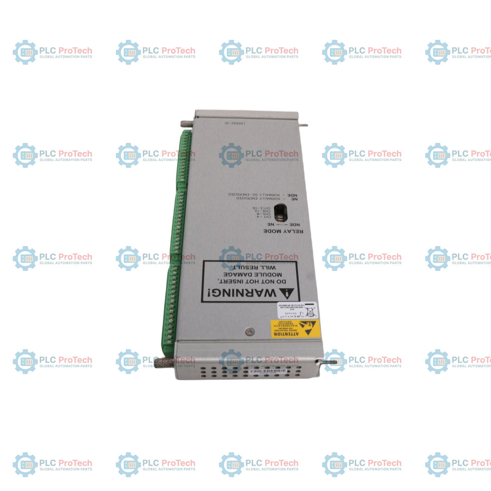
Individual hardware switch assignments on the circuit board allowing independent Normally Energized (NE) or Normally De-energized (NDE) configuration per relay.
Clear front-panel LED diagnostics providing real-time visual assessment of module health (OK), backplane communication bus activity (TX/RX), and individual channel alarm states.
Applications
Low-current alarm link interfaces connecting heavy rotating machinery protection racks to industrial PLCs and safety controllers.
Distributed logic voting and automated emergency shutdown mapping for high-criticality steam turbines, gas turbines, and compressors.
Multi-point protective trip signaling inside demanding petrochemical facilities, oil refineries, and power generation stations.
Ordering Information
Ordering Code / Component Part Number
Description
3500/33-03-00
16-Channel Relay Module complete assembly with Low Current Relays, No Agency Approvals.
A: 03
Low Current Relay Module option (utilizes Output Module with Gold Contacts).
B: 00
Agency Approval Option: None.
149992-03
Main Board Component: Low Current 16-Channel Relay Main Module with Gold-Plated Contacts.
Technical Specifications
Parameter Category
Specification Details
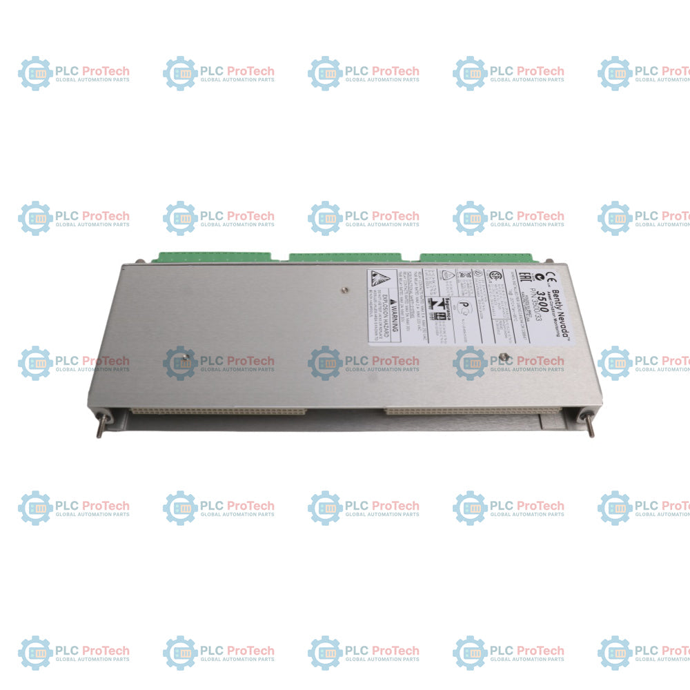
Manufacturer
Bently Nevada (Baker Hughes)
Combined Designation
3500/33-03-00 149992-03
Module Type
16-Channel Relay Module (Low Current Gold Variant)
30 Vdc at 2 A resistive / 48 Vdc at 0.2 A resistive / 125 Vdc at 0.1 A resistive / 250 Vac at 2 A resistive
Contact Operation Mode
Onboard switch-selectable for Normally De-energized (NDE) or Normally Energized (NE)
Operating Temperature
-30 degC to +65 degC (-22 degF to +150 degF)
Storage Temperature
-40 degC to +85 degC (-40 degF to +185 degF)
Relative Humidity
95%, non-condensing
Main Card Dimensions
241.3 mm x 24.4 mm x 241.8 mm (9.50 in x 0.96 in x 9.52 in)
I/O Card Dimensions
241.3 mm x 24.4 mm x 99.1 mm (9.50 in x 0.96 in x 3.90 in)
Main Module Weight
0.82 kg (1.8 lb)
I/O Module Weight
0.41 kg (0.9 lb)
Connections/Interfaces
The diagnostic readouts on the front and the physical terminations on the rear facilitate distinct interface tracking:
Component Identifier
Functional Description / Assignment
OK LED
Front panel health light; remains solid green when internal software algorithms process normally.
TX/RX LED
Front panel communication light; flashes rapidly to indicate active digital backplane traffic.
CHALRM LEDs (1 - 16)
Channel status lights; independent LEDs illuminate directly to show when a specific relay channel is tripped.
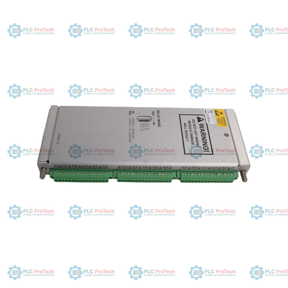
Rear Terminal Block Contacts
I/O backplane connection pins grouping Common (COM), Normally Open (NO), and Normally Closed (NC) lines.
Relay Mode Toggles
Physical multi-position dual-throw onboard switches assigning individual channel states to NDE or NE.
Installation Guidelines
Rack Positioning: Slide the complete 3500/33-03-00 149992-03 module assembly into any available full-height slot located strictly to the right of the Transient Data Interface (TDI) module.
Rear Alignment: Secure the corresponding 16-channel internal termination input/output module (such as 149986-01) into the matching rear slot directly behind the main card.
Onboard Switch Configuration: Adjust the internal physical toggle switches to determine the required Normally Energized or Normally De-energized status for each channel before sliding the board into the live slot.
Loop Voltage Verification: Confirm that the downstream instrumentation loops comply strictly with low-voltage and low-current constraints; introducing heavy inductive or high-power loads will destroy the gold-plated contact surfaces.
Logic Deployment: Open the system rack software suite to map and download the intended AND/OR safety voting matrix into the module non-volatile memory prior to system testing.
Compliance and Certifications
EMC Directives: European Community Directive 2014/30/EU (EMC Directive).
EMC Standards: EN 61000-6-2 (Industrial Immunity), EN 61000-6-4 (Industrial Emissions).
Electrical Safety: Low Voltage Directive 2014/35/EU, EN 61010-1 Standard.
RoHS Directive: 2011/65/EU European Compliance.
Hazardous Area Approvals: cNRTLus Class I, Zone 2: AEx/Ex nA nC ic IIC T4 Gc / Class I, Division 2, Groups A, B, C, and D (T4 @ Ta = -20 degC to +65 degC).
ATEX/IECEx Approvals: II 3 G Ex nA nC ic IIC T4 Gc / Ex ec nC ic IIC T4 Gc.
FAQ
What is the functional relationship between the 3500/33-03-00 code and the 149992-03 part number?
The 3500/33-03-00 represents the complete factory ordering model number specifying a 16-channel relay system configured for low-current applications, while the 149992-03 is the exact manufacturer part number printed on the physical low-current main processor board included in that specific combination.
Why is gold plating critical for the contacts on this module?
Gold plating is vital for low-current circuitry (down to 1 V, 1 mA) because standard silver contacts develop surface oxidation layers over time under low electrical loads, whereas gold resists tarnish to guarantee a clean connection path.
Can I perform a hot-swap on this module while machinery monitoring is actively running?
Yes, the unit features a fully hot-swappable architecture, allowing maintenance teams to remove or insert the card into the slot without disconnecting power or causing signal drops on adjacent monitor channels.
Does a single order of this product supply both the front processor and the rear terminal board?
When purchased as a complete surplus or spare assembly assembly under these factory specifications, it typically denotes the main card; ensure you verify whether your specific system panel requires the matching 149986-01 rear internal termination block as well.
Maintenance data connects work orders, sensor signals, asset history, costs, and technician knowledge. Used well, it improves planning, reliability, predictive maintenance, spare-parts control, and...
This article explains how integrated electric actuators, such as SMC’s e-Actuator series, are transforming industrial motion control by replacing traditional pneumatic and hydraulic systems. It...
This article explains how PLC systems perform core mathematical operations such as addition, subtraction, multiplication, division, modulo, and exponentiation within industrial automation. It shows...
The article explains several advanced Boolean logic functions used in PLC programming beyond basic AND, OR, and NOT operations. It covers how tools like truth tables, multiplexers, pulse generators,...
Boolean logic is the foundation of every PLC program. From simple machine controls to complex industrial automation systems, logic gates determine how controllers respond to changing inputs and...
Industrial firewalls play a critical role in OT cybersecurity, protecting PLC, DCS, and SCADA networks through segmentation, ingress/egress control, and IDS/IPS integration aligned with IEC 62443...
Choosing a selection results in a full page refresh.