The Bently Nevada 3500/33-04-00 149992-04 is a 16-channel failsafe relay output module used as a main or spare module in 3500 machinery protection systems. It provides 16 independently programmable relay outputs with alarm drive logic, supporting AND/OR logic combinations of alert, danger, Not-OK statuses, and measured variables from any monitor channel. Each relay output can perform voting logic and integrates with the 3500 Rack Configuration Software.
This module interfaces with PLC, DCS, SIS, and TSI systems, offering both normally de-energized (ND) and normally energized (NE) operation selectable in four groups of four channels. Front-panel LEDs indicate module status, communication activity, and channel alarm states.
It supports low current switching applications with gold-plated contacts, suitable for standard, failsafe, or hazardous area configurations. Module compatibility includes installation to the right of the Transient Data Interface (TDI) in a 3500 rack.
Features
16 relay outputs with independent programmable logic
Alarm drive logic using AND/OR conditions
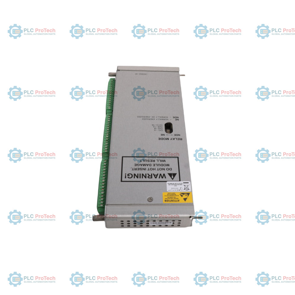
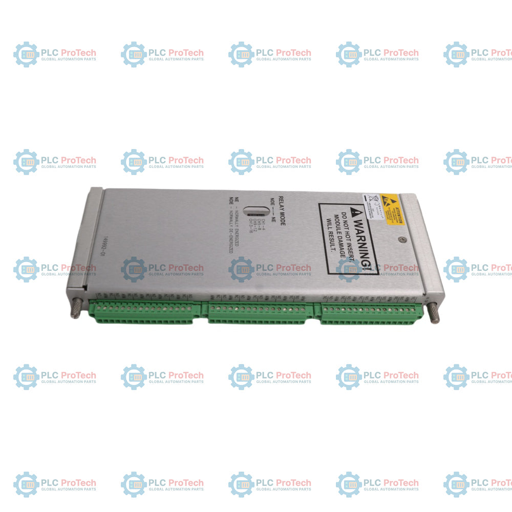
Selectable normally de-energized (ND) or normally energized (NE) operation
Front-panel LEDs for OK, TX/RX, and channel alarm status
Epoxy-sealed relays with arc suppressors (250 Vrms)
Relay life up to 10,000 cycles
Low current gold-plated contact option for 1 mA @ 1 Vdc minimum load
Ensure the rack frame is properly tied to the plant instrumentation ground before inserting modules. Field wiring shields should be terminated at the designated shield terminals on the I/O module to minimize electromagnetic interference and ensure signal integrity.
Hazardous Area Precautions
Do not disconnect field wiring or module connections while the circuit is live unless the location is verified to be non-hazardous. Live handling in explosive atmospheres can result in arc-induced ignition risks.
Module Placement
Align the main module with the chosen front slot to the right of the TDI module. Slide it firmly into the backplane connectors and tighten the panel screws. Install the matching I/O module in the corresponding slot directly on the rear of the rack assembly.
FAQ
What does the 04 option signify in this module part number?
The 04 code specifies that this is the Low Current 16-Channel Failsafe variant equipped with gold-plated contacts.
What is the minimum current rating for the gold-plated contact version?
The minimum switched current rating is 1 mA @ 1 Vdc.
Can I mix the configuration for Normally Energized and Normally De-energized modes?
Yes, the sixteen channels are split into four distinct groups of four channels, and each group is independently switch-selectable.
What is the purpose of the TX/RX LED on the front panel?
The TX/RX LED flashes to indicate active transmission and reception of communication data between this module and other rack modules.
Does this hardware package contain built-in spark protection for the contacts?
Yes, an internal 250 Vrms epoxy-sealed relay arc suppressor is standard equipment on the hardware channels.
Can this unit process individual variables from multiple monitor modules at once?
Yes, the Alarm Drive Logic can combine Alert, Danger, or Not-OK inputs from any monitor channel or combination of monitor channels within the rack.
What software tool is required to configure the voting logic pathways?
The system logic is engineered and uploaded using the 3500 Rack Configuration Software.
What happens to the relay operation if the module encounters an internal failure?
The Failsafe design ensures that when a major failure or loss of control occurs, the relays drop to their safe de-energized or default state depending on wiring.
Is it safe to exceed 5 mA when using an AC supply voltage up to 120Vac?
No, currents exceeding 5 mA on these low-current gold relays will degrade or permanently damage the contact plating.
How many slots does the complete main and I/O assembly take up?
It occupies one full-height slot on the front of the rack and one corresponding full-height slot on the rear panel.
Can I plug this module into the slot immediately adjacent to the power supply?
It must be placed in any available slot situated to the right of the Transient Data Interface module.
What does a solid light on the OK LED indicate?
A solid light confirms that the hardware is powered up, has passed initial self-tests, and is operating properly.
Maintenance data connects work orders, sensor signals, asset history, costs, and technician knowledge. Used well, it improves planning, reliability, predictive maintenance, spare-parts control, and...
This article explains how integrated electric actuators, such as SMC’s e-Actuator series, are transforming industrial motion control by replacing traditional pneumatic and hydraulic systems. It...
This article explains how PLC systems perform core mathematical operations such as addition, subtraction, multiplication, division, modulo, and exponentiation within industrial automation. It shows...
The article explains several advanced Boolean logic functions used in PLC programming beyond basic AND, OR, and NOT operations. It covers how tools like truth tables, multiplexers, pulse generators,...
Boolean logic is the foundation of every PLC program. From simple machine controls to complex industrial automation systems, logic gates determine how controllers respond to changing inputs and...
Industrial firewalls play a critical role in OT cybersecurity, protecting PLC, DCS, and SCADA networks through segmentation, ingress/egress control, and IDS/IPS integration aligned with IEC 62443...
Choosing a selection results in a full page refresh.