Product Overview
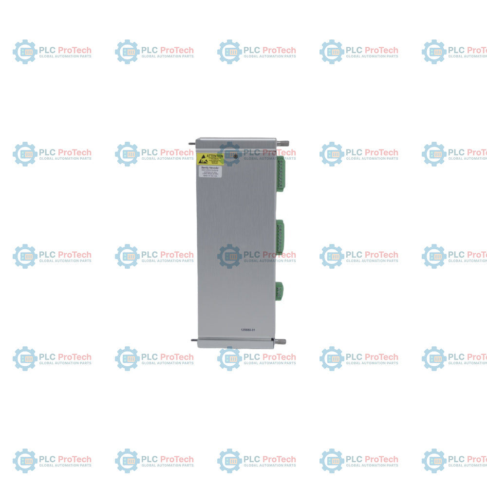
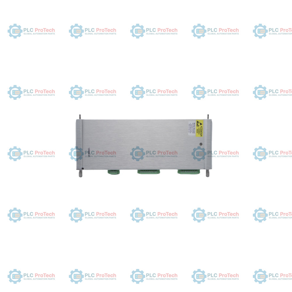
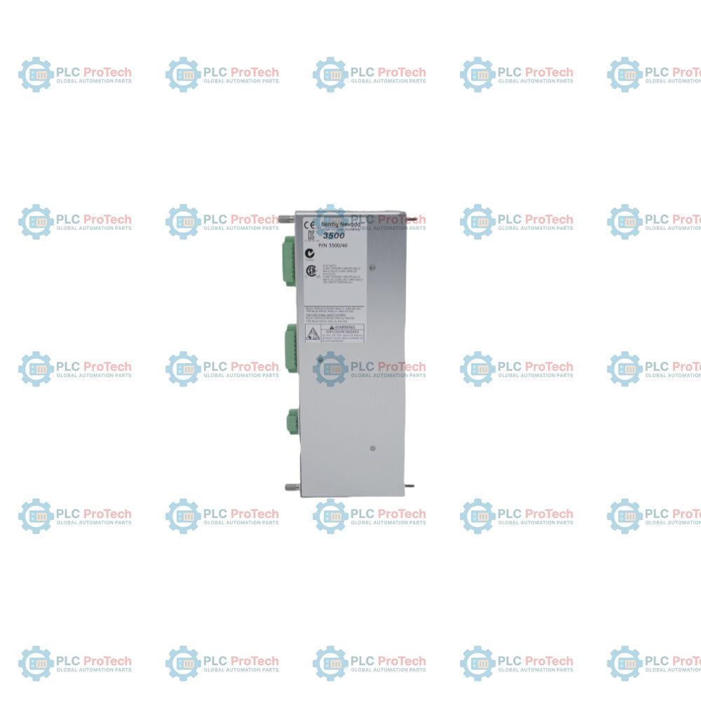
The Bently Nevada 125680-01 is a 4-channel Proximitor I/O Module with Internal Terminations engineered for the 3500 Series Machinery Protection System. Seated in the rear slot of the 3500 instrumentation rack, this module serves as the direct hardware interface linking external eddy current proximity transducers to the front-facing 3500/40M Proximitor Monitor module.
The unit provides stable sensor power excitation, receives raw analog displacement voltages, and channels these conditioned paths into the main processor card to calculate machinery metrics like radial vibration, shaft eccentricity, thrust position, differential expansion, and REBAM. Armed with an integrated screw-terminal block, the 125680-01 eliminates the need for separate external termination panels, saving critical footprint space within dense control room cabinets.
Technical Configuration
| Parameter |
Specification |
| Brand |
Bently Nevada |
| Model Number |
3500/40M (Rear Component) |
| Part Number / ID |
125680-01 |
| Product Type |
Proximitor I/O Module (Internal Terminations) |
| System Compatibility |
3500 Series Machinery Protection System |
| Channel Capacity |
4 Non-Isolated Proximity Transducer Channels |
| Signal Input Impedance |
10 kΩ for Proximitor Inputs |
| Termination Connection |
Built-in Multi-position Screw Terminal Block |
| Power Consumption |
7.7 Watts Typical |
| Transducer Support |
Bently Nevada 3300 XL 8mm, 11mm, and 25mm |
| Measurements |
Radial Vibration, Thrust, Eccentricity, REBAM |
| Dimensions (WxHxD) |
24.4 mm x 241.3 mm x 99.1 mm |
| Product Net Weight |
0.20 kg (0.44 lb) |
| Country of Origin |
United States (USA) |
Ordering Information
Turbomachinery monitoring hardware modifications dictate checking explicit spare part numbers. Procure replacements strictly matching the factory ordering codes below.
-
Main System Component Suffix: 3500/40M
-
Factory Order Part Number: 125680-01
-
Module Core Variant: Standard Full-Height Rear I/O Module
Engineering Notes & Field Wiring Guide
Transducer Signal Termination Layout
The internal termination block of the 125680-01 handles up to four field proximity sensor arrays. Each signal channel grouping contains three dedicated screw terminals:
-
VTX / Prox (+): Transducer power supply voltage rail (typically -24V DC excitation).
-
SIG / In (S): Continuous analog raw gap voltage returned from the Proximitor sensor.
-
COM / Gnd (-): Common instrumentation reference return line.
Strip conductor insulation back exactly 7 mm. Use high-grade 3-wire twisted-shielded instrumentation cables (18 AWG to 22 AWG copper) to prevent magnetic induction anomalies from distorting high-frequency signals.
Cable Shield Grounding Protocols
Terminate individual outer cable shields at the 3500 chassis frame to prevent EMI/RFI noise. Shield lines must be bundled and bonded to the unpainted rack frame grounding bar using a wide-surface ground clamp. Never tie the cable shield into the terminal block's signal common (COM) screws; doing so generates ground loops that can mask critical high-amplitude vibrations.
Live-Swapping Safety Constraints
The 3500 architecture allows hot-swapping; however, pulling a rear I/O module immediately cuts excitation power to field sensors, triggering a "Monitor Fault."
-
Toggle the rack’s front keylock switch to "PROGRAM" mode.
-
Enable software channel bypass flags via the 3500 Rack Configuration Software.
-
Proceed with physical removal to prevent downstream emergency trip relays from activating.
Maintenance & Troubleshooting FAQ
Q: What is the primary difference between the 125680-01 and external termination modules?
A: The 125680-01 contains built-in screw terminal arrays on its back faceplate, allowing field wiring to anchor directly to the module. External termination variants require high-density multi-pin ribbon cables to connect to a separate DIN-rail terminal panel mounted elsewhere.
Q: Can the 125680-01 module accept signals from non-Bently Nevada proximity sensors?
A: No. Internal pathways and scaling matrices are calibrated specifically for Bently Nevada proximity transducers. Third-party probes will break linear scale factors, invalidating measurement conversions and generating calibration errors.
Q: How do you troubleshoot an individual channel showing a persistent "NOT OK" status?
A: Measure the raw DC gap voltage across the SIG and COM terminals with a multimeter. A healthy probe displays between -4V DC and -16V DC. If the voltage is near 0V or mirrors the full -24V supply, the fault is likely a cable short or open conductor in the field rather than an I/O module failure.