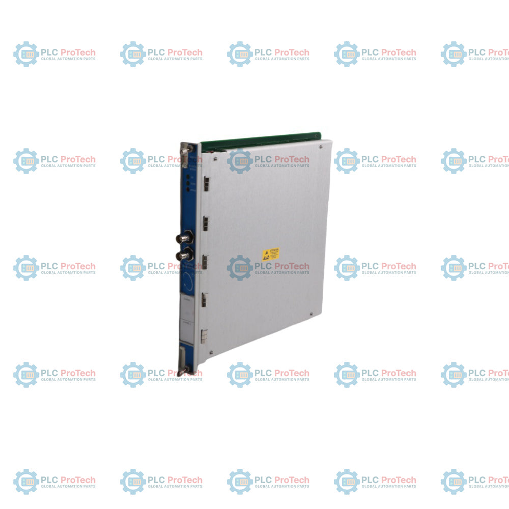
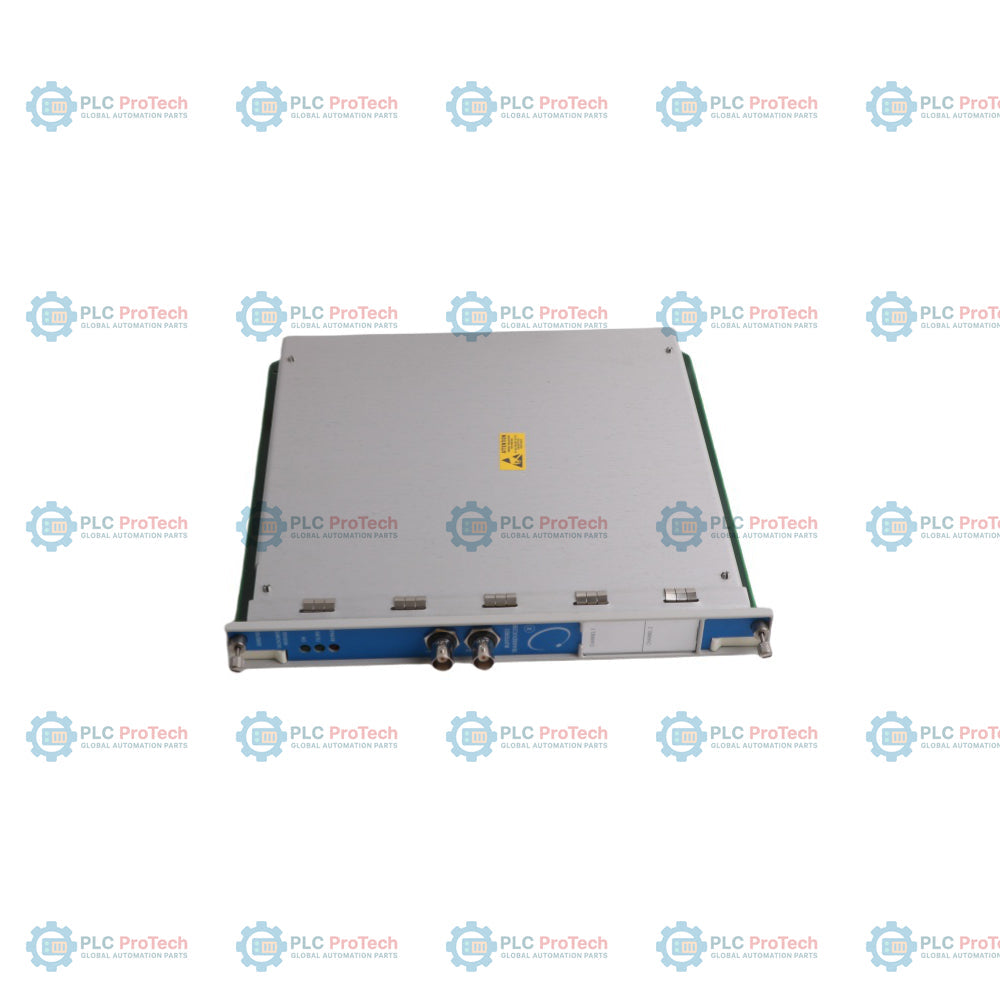
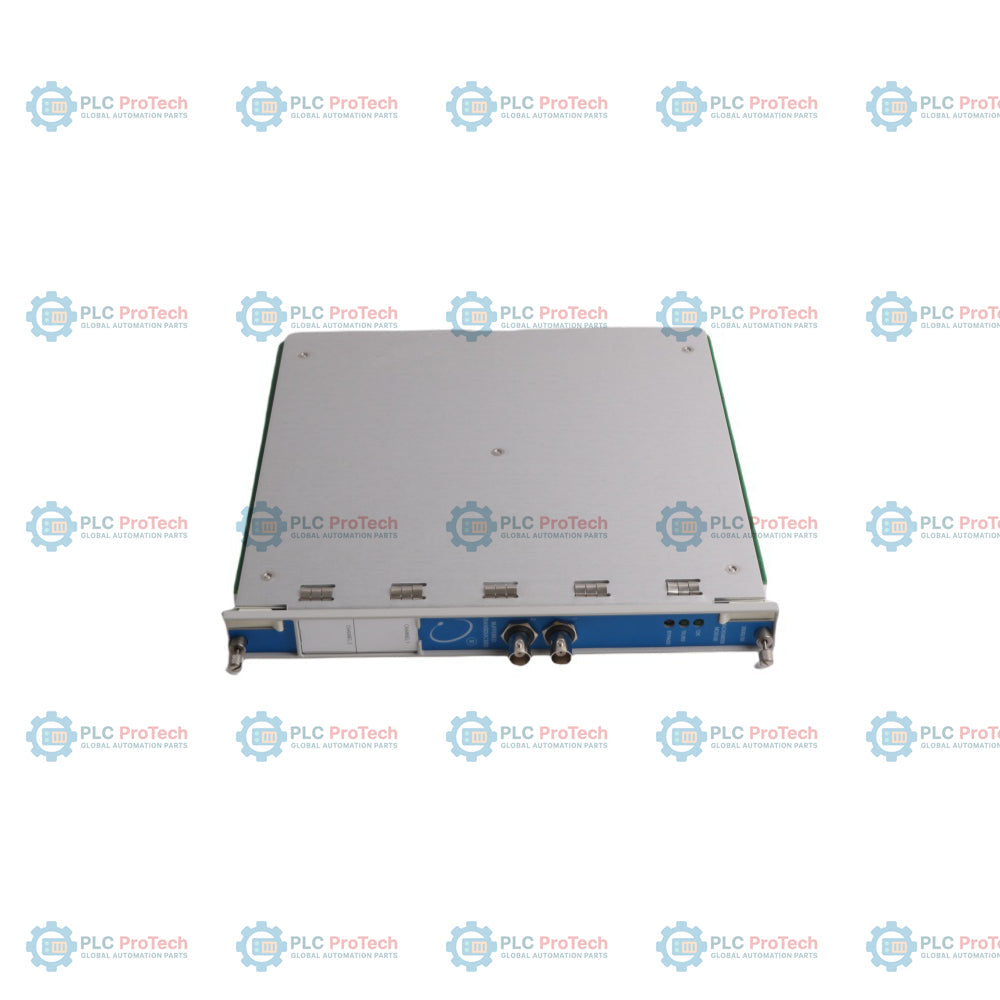
1 of 3

Bently Nevada 3500/50 133388-02 Tachometer Module

Bently Nevada 3500/50 133388-02 Tachometer Module

Only 6 item(s) left in stock
  • Manufacturer: Bently Nevada

  • Product No.: 3500/50 133388-02

  • Country of origin:United States

  • Product Type: Tachometer Module

  • Barcode: 8537101190

  • Payment: T/T, Western Union

  • Weight: 820g

  • Dimensions: 241.3 mm x 24.4 mm x 241.8 mm

  • Shipping port: Xiamen

  • Warranty: 12 months

Quantity
View full details

Description

The 3500/50, designated under spare part number 133388-02, is a 2-channel hardware component engineered to determine shaft rotative speed, rotor acceleration, or rotor direction within the 3500 Machinery Protection System. The module interfaces directly with raw proximity probe transducers or passive magnetic pickups to monitor physical asset dynamics. Acting as an analytical interface layer, it continuously compares acquired frequency data against user-programmable alarm setpoints, changing states to trip automated safety alarms when thresholds are exceeded. Configurable through the 3500 Rack Configuration Software, the module can supply conditioned Keyphasor signals to the backplane network, eliminating the need for independent Keyphasor hardware installations. The instrument outputs an independent +4 to +20 mA analog recorder signal for each measurement channel to supply plant operations and logging utilities with deterministic diagnostic indicators.

Features

  • Dual independent channel capabilities for multi-point frequency or rotational direction tracking.
  • Versatile sensor acceptance supporting both eddy current proximity systems and passive magnetic pickups.
  • Four standard firmware options comprising speed monitoring, speed band, zero speed, acceleration, and reverse rotation tracking.
  • Integrated peak hold logic capturing maximum forward speed, maximum reverse speed, and cumulative reverse rotations.
  • Internal rack signal distribution delivering conditioned Keyphasor reference data to adjacent 3500 series monitors.

Applications

  • Industrial steam and gas turbine rotor shaft speed tracking and peak rotation monitoring.
  • Centrifugal process gas compressor acceleration observation and emergency shutdown interface.
  • Large-scale cooling tower fan zero speed validation and reverse rotation notification.
  • High-horsepower industrial gearbox input-to-output shaft speed ratio monitoring.

Ordering Information

Option Code Description
3500/50-AXX-BXX


Tachometer Module 

A: I/O Module Type  
01 I/O Module with Internal Terminations 
02 I/O Module with External Terminations 
03 TMR I/O Module with External Terminations 
04 I/O Module with Internal Barriers and Internal Terminations 
B: Agency Approval Option  
00 None 
01 CSA/NRTL/C 
C: Monitor Use  
01 Speed Measurement 
02 Reverse Rotation 
Spares  
133388-02 3500/50 Tachometer Module

Technical Specifications

Parameter Specification
Manufacturer Bently Nevada 
Model 3500/50 
Part Number 133388-02 
Signal Input Channels 2 proximity probe transducers or magnetic pickups 
Input Voltage Signal Range +10.0 V to -24.0 V 
Standard Input Impedance 20 kΩ 
TMR Input Impedance 40 kΩ 
Internal Barrier Input Impedance 7.15 kΩ 
Nominal Power Consumption 5.8 Watts typical 
Recorder Proportional Output +4 to +20 mA DC 
Recorder Voltage Compliance 0 to +12 Vdc across load 
Recorder Load Resistance Range 0 to 600 Ω 
Transducer Power Supply Output -24 Vdc, 40 mA maximum per channel 
Maximum Supported Input Frequency 20 kHz 
Maximum Full Scale Speed Range 99,999 rpm 
Proximity Probe Frequency Limits Minimum 0.0167 Hz (1 rpm for 1 event/revolution) 
Magnetic Pickup Frequency Limits Minimum 3.3 Hz 
RPM Accuracy (< 100 rpm) Within ±0.1 rpm 
RPM Accuracy (100 to 10,000 rpm) Within ±1 rpm 
RPM Accuracy (> 10,000 rpm) Within ±0.01% of true shaft speed 
Rotor Acceleration Accuracy Within ±20 rpm/min 
Auto Triggering Amplitude Minimum 1 volt peak-to-peak 
Manual Triggering Scope +9.5 Vdc to -23.5 Vdc with 500 mV peak-to-peak minimum 
Adjustable Trigger Hysteresis User selectable from 0.2 to 2.5 volts 
Alarm 1 Delay Range 1 to 60 seconds in 1 second intervals 
Alarm 2 Delay Range 1 to 60 seconds in 0.1 second intervals 
Operating Temp (Standard I/O) -30 Celsius to +65 Celsius (-22 Fahrenheit to +150 Fahrenheit) 
Operating Temp (Barrier I/O) 0 Celsius to +65 Celsius (32 Fahrenheit to +150 Fahrenheit) 
Storage Temperature Limits -40 Celsius to +85 Celsius (-40 Fahrenheit to +185 Fahrenheit) 
Operating Humidity Max 95% non-condensing relative humidity 
Main Monitor Module Weight 0.82 kg (1.8 lbs) 
I/O Module Weight (Non-Barrier) 0.20 kg (0.44 lbs) 
I/O Module Weight (Barrier) 0.46 kg (1.01 lbs) 
Main Monitor Dimensions 241.3 mm x 24.4 mm x 241.8 mm 
I/O Module Dimensions (Non-Barrier) 241.3 mm x 24.4 mm x 99.1 mm 
I/O Module Dimensions (Barrier) 241.3 mm x 24.4 mm x 163.1 mm 
Chassis Rack Requirements 1 full-height front slot and 1 full-height rear slot 

Connections/Interfaces

Terminal / Connector Pin Function
CH1 BNC (Front Face) Buffered Transducer Coaxial Output for Channel 1 
CH2 BNC (Front Face) Buffered Transducer Coaxial Output for Channel 2 
I/O TRANSDUCERS (CHI) PWR / COM / SIG / SHLD Terminal Blocks for Sensor Input 1 
I/O TRANSDUCERS (CH2) PWR / COM / SIG / SHLD Terminal Blocks for Sensor Input 2 
CONTACTS Terminal Block RESET (PRST1 / PRST2) and Zener Barrier Enable Interlocks 
BUFFERED TRANSDUCERS Block Buffered Euro-style Output Pins for External Oscilloscopes 
RECORDER OUTPUTS Block Dedicated COM / REC1 / REC2 / SHLD Current Loop Interfaces 

Installation Guidelines

  • Grounding Control: Terminate field sensor cable shields explicitly at the designated SHLD pins on the rear termination blocks to build an effective faraday path against high-frequency electrical noise.
  • Slot Alignment: Insert the main front module into any available full-height slot location, pushing firmly along the alignment tracks until the card engages with the rack backplane power lines.
  • Sensor Exclusions: Do not map magnetic pickup inputs to zero speed or reverse rotation notification functions, as low shaft velocity cannot generate sharp edge signals for proper trigger interpretation.
  • Ventilation Integrity: Ensure clearance tracks are maintained on both the front face and rear interface regions to facilitate ambient forced-air cooling paths through the instrument chassis.

Compliance and Certifications

  • CE Mark Directives: EN50081-2 Radiated and Conducted Emissions (Class A), EN50082-2 Industrial Susceptibility Standard.
  • Low Voltage Directives: EN 61010-1 Environmental Safety Requirements for Electrical Equipment.
  • CSA / NRTL / C: Certified for Class I, Division 2, Groups A through D installations when combined with matching standard termination modules.

Technical & Procurement FAQ

Q: Can this instrument independently control plant machinery overspeed trip valves? A: No, Bently Nevada tachometer modules are not engineered as components for standalone speed control or direct overspeed protection, as they lack the critical structural redundancy needed for machinery trip functions.

Q: What is the physical operational difference between part number 133388-02 and the 3500/50 series designation? A: The 3500/50 identifies the overall functional tachometer module design family, while the reference 133388-02 dictates the specific warehouse spare component identifier for the front card assembly.

Q: Is manual calibration necessary for the analog output loop upon deployment? A: No field-level calibration routines are necessary, since all transmitter input ranges, voltage thresholds, and discrete parameters are processed digitally using the 3500 software layer.

Q: Can a magnetic pickup be safely assigned to verify reverse rotation behavior? A: No, passive magnetic pickups fail to deliver a distinct or clean signal edge during slow or stopping shaft cycles, which can cause severe faults or incorrect direction tracking within the logic layer.

Q: How does a sudden external short circuit on the analog recorder loop affect overall speed tracking? A: The primary speed tracking, alarm monitoring, and backplane processing operations remain completely uninfluenced by short-circuit faults across the external recorder line loops.

Product Documentation

Technical Datasheet (PDF) Complete specifications and technical drawings.
Download Now

Global Express Shipping

  • Standard Delivery: 4-6 Business Days via DHL, FedEx, and UPS.
  • Express Dispatch: Same-day dispatch for in-stock orders placed before 2:00 PM (GMT+8).
  • Worldwide Coverage: Serving over 150 countries, including rapid delivery to Saudi Arabia and UAE.

Returns & Warranty

  • 30-Day Guarantee: Returns accepted for in-stock products in original, factory-sealed packaging.
  • 12-Month Warranty: Every industrial component is backed by our professional technical warranty.

Orders are processed and delivered Monday-Friday (excluding public holidays).


For full eligibility, restocking fees, and international return details, please view our official Refund & Return Policy .

TECHNICAL SPECIFICATIONS

Color pattern
Silver Greyish White
Country of origin
United States
Power source
DC Power

Recently Viewed Products

Technical knowledge

Guide to Robotic Grippers: From Delicate Handling to Heavy-Duty Automation

Modern robotic grippers are evolving beyond traditional mechanical jaws. From gecko-inspired adhesive systems and soft food-grade grippers to AI-powered warehouse tools, advanced gripping...

Throwback: How Early Electric Motors Changed Underground Mining

From rope-driven DC compressors to battery-powered mine carts, early mining operations marked a turning point in industrial electrification. This article explores how electric motors transformed...

Factory I/O: A Modern PLC Simulation Tool for Industrial Automation Training

Factory I/O is transforming PLC education by delivering immersive 3D industrial simulations for students, engineers, and maintenance teams. The platform bridges the gap between theory and real-world...

Programming Single-Axis Motion Cycles on a CMZ Servo Drive

This tutorial examines how onboard PLC functionality inside a CMZ SBD servo drive can execute standalone motion programs, including homing logic, position control, and cyclic axis movement without an...

Single-Axis Motion Control Setup with CMZ Servo Drives

This tutorial explores the commissioning of a single-axis servo motion system using a CMZ SBD drive, covering hardware setup, axis scaling, homing configuration, and safe motion verification for...

Mitsubishi FX PLC Integration With FR-D700 VFD and HMI Control

This tutorial explains how Mitsubishi FX PLCs integrate with FR-D700 VFDs and HMI panels for forward/reverse motor control. It covers wiring logic, parameter configuration, ladder programming, and...