Product Overview
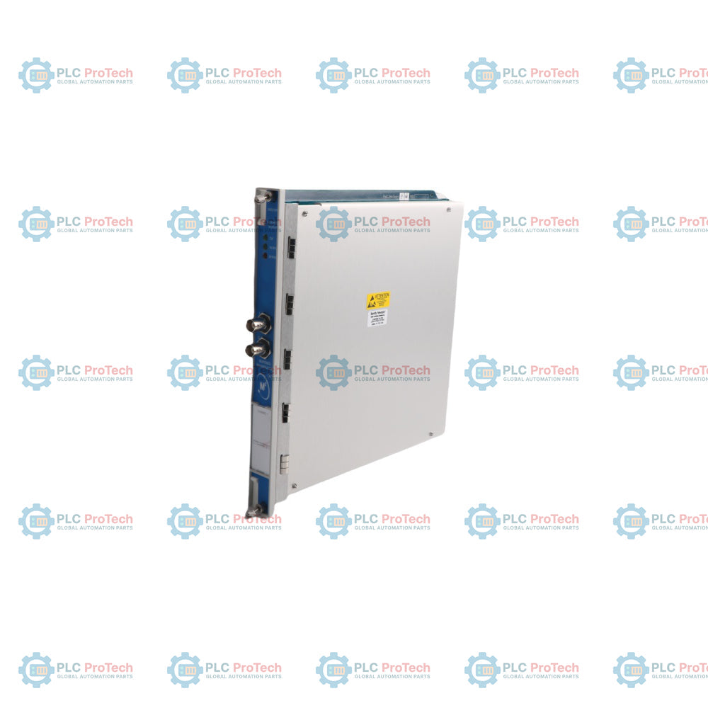
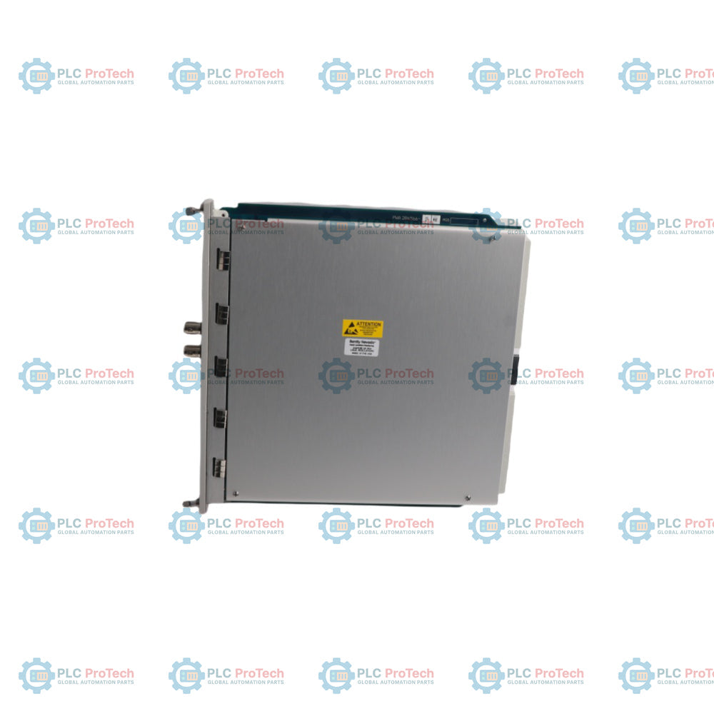
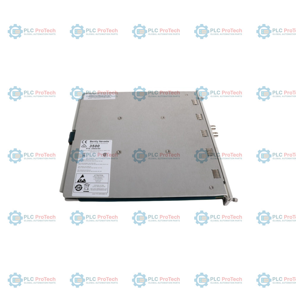
The 3500/50M 286566-02 is a high-performance, dual-channel tachometer module designed for the Bently Nevada 3500 Machinery Protection System. Deployed globally across heavy industries including thermal power plants, oil refineries, and large-scale mining operations, this module processes inputs from passive magnetic pickups or proximity probes to provide precision shaft speed, rotor acceleration, and reverse rotation indicators. By continuously cross-referencing live data with programmable alarm setpoints, it executes instantaneous alarm generation to prevent catastrophic overspeed events. The module drastically reduces plant downtime by providing stable, conditioned Keyphasor signals straight to the rack backplane, eliminating the need for dedicated Keyphasor hardware in the same rack enclosure.
Technical Configuration
The 286566-02 functions as a primary processing card within the 3500/50M tachometer architecture, delivering dual-channel sensor processing and independent configuration options via the 3500 Rack Configuration software.
-
Speed Tracking Modes:Supports standard speed monitoring, multi-band speed alarming, zero-speed alerts, rotor acceleration tracking, and reverse rotation notification.
-
Peak Data Logging:Features an on-board peak hold capability that permanently logs maximum forward speed, maximum reverse speed, and cumulative reverse rotation events until a manual or remote reset command is given.
-
Signal Interconnectivity: Routes internal conditioned Keyphasor pulses across the rack backplane, enabling simultaneous multi-channel phase tracking for adjacent vibration monitors.
-
Hardware Interface: Features front-panel buffered transducer outputs via coaxial connections alongside dedicated LEDs indicating module OK status, active serial communication TX/RX, and system bypass state.
Technical Specifications
| Parameter |
Specification |
| Model |
3500/50M 286566-02 |
| Brand |
Bently Nevada |
| Origin |
United States |
| Channel Count |
2 Independent Channels |
| Input Signal Range |
+10.0 VDC to -24.0 VDC |
| Input Impedance |
20 kOhm (Standard) / 40 kOhm (TMR) |
| Transducer Compatibility |
Proximity Probes, Passive Magnetic Pickups |
| Maximum Input Frequency |
20 kHz |
| RPM Measurement Range |
1 to 99999 rpm |
| RPM Accuracy (< 100 rpm) |
±0.1 rpm |
| RPM Accuracy (100 to 10000 rpm) |
±1 rpm |
| RPM Accuracy (> 10000 rpm) |
±0.01% of true shaft speed |
| Analog Recorder Outputs |
4 to 20 mA |
| Power Consumption |
5.8 watts typical |
| Operating Temperature |
-40 to 70 deg C |
| Weight |
0.82 kg |
| Dimensions (H x W x D) |
244.3 mm x 24.4 mm x 241.8 mm |
Operational FAQs
Can the 3500/50M 286566-02 module be hot-swapped while the 3500 system is powered?
Yes. The 3500/50M tachometer card is designed for live insertion and removal within a powered 3500 rack. However, to prevent unintended trip signals on downstream machinery control components, the operator must place the associated protection loops or relay outputs into bypass before pulling the module.
How does the module determine the threshold for passive magnetic pickups versus proximity probes?
The module configuration software allows operators to toggle between Auto Threshold and Manual Threshold modes. Auto Threshold works for any speed input above 1 rpm (0.0167 Hz) with a minimum peak-to-peak amplitude of 1 volt. Manual Threshold allows direct adjustment from +9.5 VDC down to -23.5 VDC.
What indicates a catastrophic internal circuit failure versus a sensor line fault?
The front-panel OK LED will turn off completely or flash erratically if internal hardware diagnostics fail. If the fault resides in the field wiring or probe tip gap, the OK LED will illuminate red, indicating a Not OK field transducer status, while the internal data registers switch to an invalid data flag state.
Field Commissioning and Safety Directives
-
Signal Cable Shielding: Terminate all external proximity sensor or magnetic pickup shields at the 3500 system's I/O module ground bus terminal bar. Never ground the shield at both ends to ensure ground loops do not corrupt high-frequency pulse inputs.
-
Buffered Output Isolation: The front-panel coaxial buffered outputs are short-circuit protected. Technicians can hook up portable vibration data collectors or external frequency analyzers directly to the front face without interrupting the machinery protection loop.
-
Target Wheel Design Parameters: Ensure the speed sensing target wheel or keyway conforms to the 3500/50M technical manual specifications. The configuration must be set precisely between 1 and 255 events per revolution to guarantee accurate acceleration computations.
-
Recorder Output Calibration: When using the 4 to 20 mA recorder outputs for DCS speed replication, verify that the load resistance does not exceed 600 Ohms to prevent signal clipping and maintain calibration linearity.