Description
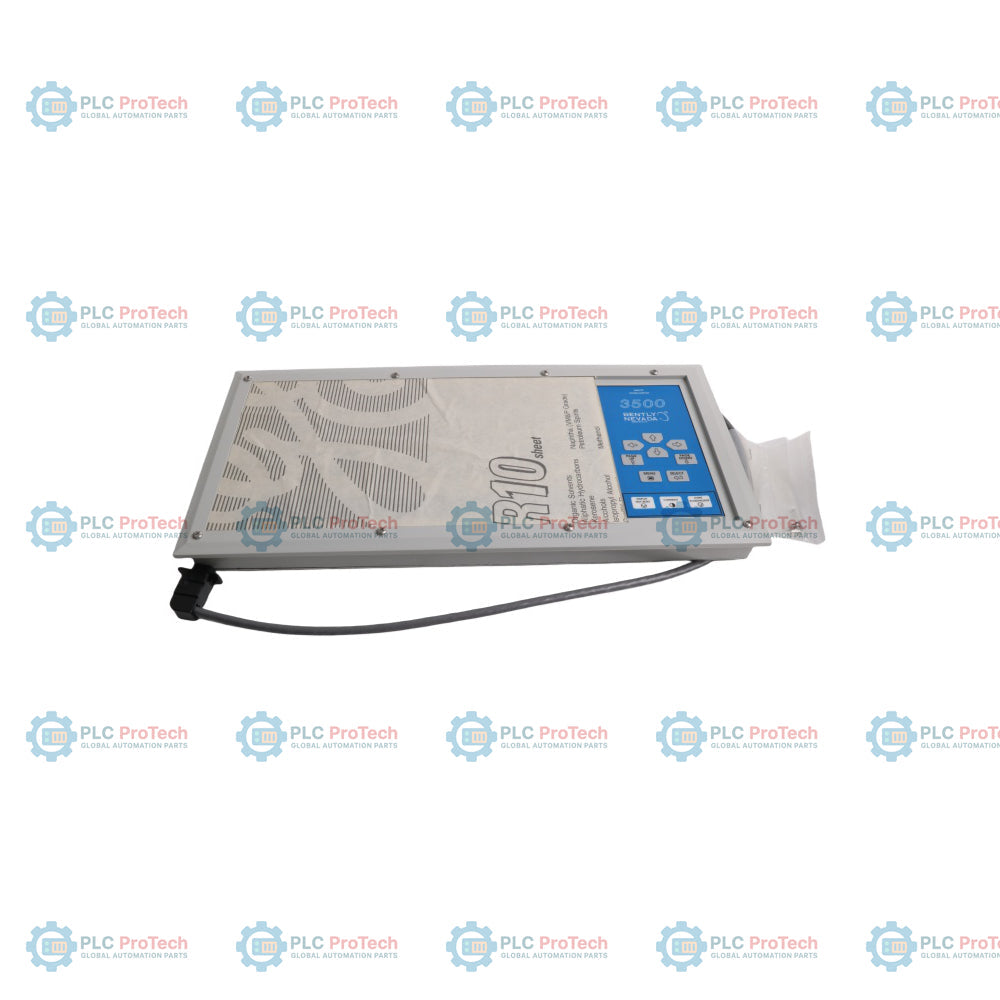
The 3500/93 display system is used for local visualization of rack monitoring data within the Bently Nevada 3500 Machinery Protection System. The 135785-01 display unit provides an LCD interface for viewing channel measurements, alarm conditions, rack status information, and other monitored variables from installed modules.
The display assembly operates together with a display interface module and a display interface I/O module. Front membrane keypad controls allow operators to navigate through channel data, alarm events, and rack operating conditions directly from the display panel.
A single 3500 rack can support up to two display units for additional monitoring visibility in machinery protection cabinets or remote operator locations. The display can be mounted directly on the rack front panel or installed remotely in a separate enclosure depending on system layout requirements.
Front-panel LEDs provide visual indication of channel status, rack condition, and active alarm states during operation and maintenance activities.
Features
- Consolidates and displays real-time machinery parameter data collected from all active rack channels.
- Built-in keypad control panel enables seamless operator navigation and localized display interface control.
- Integrated multi-segment LED system provides clear indications for Channel Status, New Alarm Events, Display Unit Status, and Rack Status.
- Flexible physical mounting infrastructure accommodates varied site layouts (System Face Mount, Rack Mount, Panel Mount, and Independent Mount).
- Robust design tailored for integration into highly demanding physical industrial environments.
Applications
- Distributed machinery status visualization across large-scale industrial plant floors.
- Critical alarm event oversight and field-level troubleshooting on 3500 monitoring enclosures.
- Localized parameter display for power generation steam/gas turbines and large centrifugal compressors.
- Control panel integration for specialized marine, petrochemical, and oil and gas machinery skids.
Ordering Information
- 3500/93: System Display System
- 135785-01: 3500/93 Display Unit Spare
- 137224-01: System Mount Assembly
- 04344178: 10-32 x 0.37 Phillips pan head screw
- 04309007: 4-40 x 0.62 Phillips pan head screw
Technical Specifications
| Parameter |
Specification |
| Manufacturer |
Bently Nevada |
| Country of Origin |
USA |
| Product Component |
Display Unit |
| Display Element |
LCD Module (Reflective version without backlight / Transflective version with backlight) |
| User Interface |
Membrane-switch Keypad |
| Visual Indicators |
LCD Machine Parameter Display, Channel Status LEDs, New Alarm Event LED, Display Unit Status LED, Rack Status LEDs |
| Supported Displays Per Rack |
Up to 2 System Displays |
| Operating Temperature |
-20 degC to 65 degC (-4 degF to 149 degF) |
| Storage Temperature |
-30 degC to 80 degC (-22 degF to 176 degF) |
| Humidity |
95% non-condensing |
| Radiated/Conducted Emissions |
EN 55011, Class A (under EMC Directive EN 50081-2) |
| Electrostatic Discharge Immunity |
EN 61000-4-2, Criteria B |
| Radiated Susceptibility |
ENV 50140, Criteria A |
| Electrical Fast Transient Immunity |
EN 61000-4-4, Criteria B |
| Surge Capability |
EN 61000-4-5, Criteria B |
| Safety Requirements Standard |
EN 61010-01 (Low Voltage Directive) |
Connections/Interfaces
| Connector Pin / Port |
Function |
| D-Sub Interface Cable |
Interconnects the 135785-01 Display Unit to the host 3500/93 Display Interface Module |
Installation Guidelines
-
Slot Restrictions: When choosing the System Face Mount configuration, the associated 3500/93 Display Interface Module must be installed specifically in slot 15 of the 3500 rack.
-
Compatibility Check: Do not attempt to use the 3500/93 System Face Mount options with a 3500/05 or 3500/05 A02 Mini-rack, as these physical configurations are incompatible.
-
Hardware Assembly: Mount the Display Unit to the system mount assembly (137224-01) using exactly four 10-32 x 0.37 Phillips pan head screws.
-
Cable Connection: Fasten the primary D-Sub interface cable securely to the rear panel of the Display Interface Module before closing the mount frame structures.
-
Chassis Attachment: Open the frames of the system mount assembly at the pivoting points and attach them securely to the rack rails via four 4-40 x 0.62 Phillips pan head screws.
Compliance and Certifications
- CSA-NRTL/C Class I, Division 2, Groups A, B, C, D (T4 at Tamb = 65 degC)
- CE Mark
FAQ
What is the function of the 135785-01 component in a 3500/93 setup?
It is the external Display Unit that provides the physical LCD, status LEDs, and a keypad interface for machinery tracking.
How many system display units can be active on a single 3500 rack?
A single 3500 monitoring system can support a maximum configuration of up to two 3500 System Displays.
What types of visual notification LEDs are built into the front panel face?
The faceplate includes designated LEDs indicating Channel Status, New Alarm Events, Display Unit Status, and overall Rack Status.
What are the primary mounting arrangements for this display unit?
The unit can be implemented using System Face Mount, Rack Mount, Panel Mount, or Independent Mount configurations.
Are there slot restrictions for the interface card when using a face mount assembly?
Yes, for a System Face Mount setup, the 3500/93 Display Interface Module must be installed in slot 15 of the rack.
Can I utilize the face mount configuration with a Bently Nevada mini-rack?
No, the 3500/93 System Face Mount option is completely incompatible with the 3500/05 and 3500/05 A02 Mini-racks.
What hardware kit is required for executing a typical system face mount?
It requires a 137224-01 System Mount Assembly, four 10-32 x 0.37 screws, and four 4-40 x 0.62 screws.
What cable interface handles the link between the display and the interface module?
The link is established through a dedicated D-Sub interface connection cable.
Does this item include the underlying backplane display interface module?
No, the 135785-01 part number refers specifically to the Display Unit spare; interface cards must be sourced separately.
What environmental humidity parameters must be maintained during active operation?
The equipment must operate within a relative humidity limit of up to 95%, non-condensing.