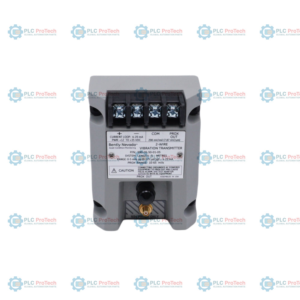
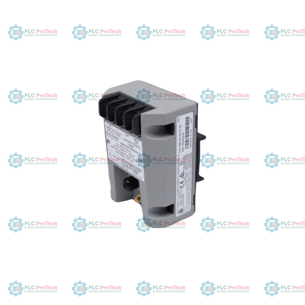
The 990-05-50-01-01 is a two-wire, loop-powered vibration transmitter designed primarily for original equipment manufacturers (OEMs) of centrifugal air compressors, small pumps, motors, or fans. This device accepts an input signal from a non-contacting 3300 NSv proximity probe and its matching extension cable. It conditions the incoming transducer signal into appropriate peak-to-peak vibration amplitude engineering units and provides a proportional 4 to 20 mA industry-standard output signal directly to a machinery control system where alarm logic and protection processes occur.
Equipped with an integrated Proximitor sensor, the 990-05-50-01-01 eliminates the requirement for an external standalone proximitor unit, reducing cabinet footprint. The encapsulated potted construction makes it highly reliable in harsh, high-humidity environments. For auxiliary diagnostic purposes, the unit includes non-isolated PROX OUT and COM terminals along with a coaxial connector to supply dynamic vibration data and gap voltage outputs.
Features
Integrated Proximitor Sensor: Combines the electronics within the transmitter casing, requiring no additional separate processing units.
Dynamic Diagnostic Outputs: Features non-isolated PROX OUT and COM terminals alongside a coaxial connector to deliver unfiltered dynamic vibration and gap voltage measurements.
Streamlined Calibration: Includes non-interacting zero and span potentiometers beneath the primary label to support effortless field loop adjustment.
Quick Loop Verification: Integrates a Test Input pin allowing rapid validation of loop signal outputs via a function generator.
Not OK / Signal Defeat Circuitry: Intercepts faulty inputs from loose connections or damaged proximity probes to immediately suppress false alarms by dropping the loop signal below 3.6 mA.
Potted Casing Construction: Optimized for high-humidity deployment up to 100% condensing environments.
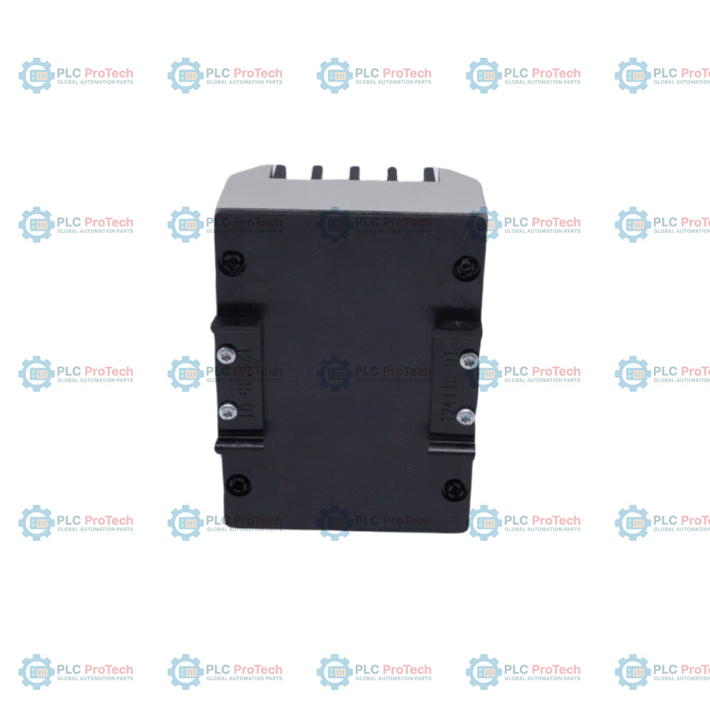
Versatile Mounting Hardware: Supports standard choice of 35 mm DIN-rail clips or bulkhead mounting configurations.
Applications
Centrifugal air compressors
Industrial small pumps
Electric motors
Cooling and ventilation fans
Rotating machinery overall vibration trending
Ordering Information
Model / Suffix Code
Option Selection
Selection Description
990
Product Model
Vibration Transmitter
-05
Full-scale Option
0-5 mils pp (0-125 micrometers pp)
-50
System Length Option
5.0 meters (16.4 feet) system length
-01
Mounting Option
35 mm DIN rail clips included
-01
Agency Approval Option
CSA Division 2 regulatory approval
Technical Specifications
Parameter Category
Specification Details
Input Specifications
Accepts 1 non-contacting 3300 NSv Proximity Probe and extension cable
Power Input Requirements
Requires +12 to +35 Vdc input at the transmitter terminal
Signal Output Type
4 to 20 mAdc over specified full-scale range in 2-wire configuration
4 to 20 mA Loop Accuracy
Within ±1.5% over specified full-scale range (rated from TEST signal input to voltage across a 250 ohm loop resistance)
Target Probe Gap
Gapped between 0.5 and 1.75 mm (20 and 55 mils) from target
Maximum Loop Resistance
1,000 ohm including cable at 35 Vdc
Current Limiting
23 mA typical
Loop Adjustments
Non-interacting external zero and span adjustments
NOT OK / Signal Defeat Timing
Output drops to less than 3.6 mA within 100 microseconds after Not OK; restores within 2-3 seconds after removal
Power-up Inhibit Duration
Stays at less than 3.6 mA for 2 to 3 seconds after power application
Prox Out Output Impedance
10 kohm output impedance calibrated for a 10 Mohm load
Prox Out Linear Range
1.4 mm (55 mils); begins at approximately 0.25 mm (10 mils) from target surface
Prox Out Incremental Scale Factor
7.87 mV/micrometer (200 mV/mil) ±6.5% typical over linear range; worst case ±10%
Prox Out Typical Noise Level
50 mV pp
Temperature Stability
Scale factor remains within ±10% of 7.87 mV/micrometer from 0 degC to +70 degC (+32 degF to +158 degF)
Frequency Response
5 Hz to 6,000 Hz +0, -3 dB
Minimum Target Size
9.5 mm (0.375 in) diameter
Prox Out Coaxial Cable Limit
Maximum cable distance is 3 meters (10 feet) for Proximitor Sensor BNC output
Transmitter Operating Temp
-35 degC to +85 degC (-31 degF to +185 degF)
Transmitter Storage Temp
-52 degC to +100 degC (-62 degF to +212 degF)
Probe Operating/Storage Temp
-52 degC to +177 degC (-62 degF to +351 degF)
Relative Humidity Limits
100% condensing, non-submerged, with protection of coaxial connectors
Wiring Specifications: Use standard 2-conductor, twisted, shielded 1.0 mm2 (18 AWG) cable (part number 02173006) for loop wiring and terminal-strip PROX OUT runs. Maximum acceptable loop wire path length is 13 km (8 miles).
Loop Resistance Restrictions: Ensure that the total loop resistance satisfies the mechanical formulation: RLOOP = 43.5 x (Vps - 12) ohms. Exceeding the maximum resistance region limits full-scale current outputs below 20 mA.
PROX OUT Phasing & Isolation: The phase of the PROX OUT raw diagnostic output signal is natively inverted compared to standard Bently Nevada outputs. Never directly connect grounded AC-powered diagnostic gear to the PROX OUT port to protect against false trip conditions. Use the specialized 122115-01 Test Adapter to introduce necessary dynamic voltage inversion and signal isolation.
Enclosure Grounding and Shielding: Terminate cable shields safely at the instrumentation common end to mitigate severe EMI/RFI noise pickup. Verify probe coaxial cables are protected from industrial moisture intrusion via connector protectors or fluorosilicone boots.
Thread Engagement Boundaries: Strictly respect nominal installation torque and maximum thread engagement lengths (12 mm for M8x1, 15 mm for M10x1) to avoid mechanical binding or physical housing failures.
Compliance and Certifications
FCC: Complies with Part 15 of FCC Rules
EMC Directives: EN 61000-6-2, EN 61000-6-4, EMC Directive 2014/30/EU
ATEX Directive: 2014/34/EU
RoHS: RoHS Directive 2011/65/EU, China RoHS 15-year EFUP (SJ/T 11364-2024)
Maritime: ABS 2009 Steel Vessels Rules
North American Approvals: cNRTLus Class I, Division 2, Groups A, B, C, D (T5 @ Ta = +85 degC, Type 4)
Hazardous Area ATEX/IECEx Ratings:
II 1 G Ex ia IIC T4 Ga (T4 @ Ta = -30 degC to +85 degC)
II 3 G Ex ec IIC T4 Gc (T4 @ Ta = -30 degC to +85 degC)
FAQ
What is the function of the Not OK/Signal Defeat circuit on the transmitter?
The circuit detects internal or environmental faults such as broken proximity probe hardware or unsecured cable interfaces. When an issue occurs, it rapidly forces the loop output current down to less than 3.6 mA within 100 microseconds, suppressing downstream false protection triggers.
Can a standard oscilloscope be attached directly to the coaxial output plug?
Directly connecting mains-powered, grounded AC diagnostic test gear to the raw PROX OUT BNC or terminal strip can create ground loops and generate false alarms. For safe dynamic diagnostic analysis, a 122115-01 Test Adapter is required to correctly invert and isolate the signal.
What power supply range is required for standard 2-wire loop operation?
The device operates on a 2-wire transmitter network and requires a DC supply voltage input between +12 Vdc and +35 Vdc measured right across the terminal blocks.
How does the power-up inhibit feature behave during system startup sequences?
Upon receiving loop power, the device forces its output signal to drop below 3.6 mA for a duration of 2 to 3 seconds. This initialization delay keeps the machinery control logic from confusing startup power transients with valid over-vibration signals.
Maintenance data connects work orders, sensor signals, asset history, costs, and technician knowledge. Used well, it improves planning, reliability, predictive maintenance, spare-parts control, and...
This article explains how integrated electric actuators, such as SMC’s e-Actuator series, are transforming industrial motion control by replacing traditional pneumatic and hydraulic systems. It...
This article explains how PLC systems perform core mathematical operations such as addition, subtraction, multiplication, division, modulo, and exponentiation within industrial automation. It shows...
The article explains several advanced Boolean logic functions used in PLC programming beyond basic AND, OR, and NOT operations. It covers how tools like truth tables, multiplexers, pulse generators,...
Boolean logic is the foundation of every PLC program. From simple machine controls to complex industrial automation systems, logic gates determine how controllers respond to changing inputs and...
Industrial firewalls play a critical role in OT cybersecurity, protecting PLC, DCS, and SCADA networks through segmentation, ingress/egress control, and IDS/IPS integration aligned with IEC 62443...
Choosing a selection results in a full page refresh.