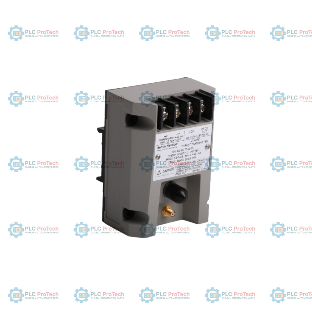
The Bently Nevada 991-06-70-01-05 is a two-wire, loop-powered thrust transmitter designed to measure the relative axial position of a rotating machine shaft. It accepts input from a 3300 NSv proximity probe and extension cable, converting the proximity signal into a proportional 4 to 20 mA current output. This device integrates directly with Programmable Logic Controllers (PLCs), Distributed Control Systems (DCSs), and SCADA networks to provide continuous machinery protection and condition monitoring. Typical industrial applications include small steam turbines, pumps, fans, and compressors where a full machinery protection system monitor rack is not required.
Features
Two-wire, 4 to 20 mA loop-powered current output
Designed for non-contacting shaft axial displacement measurement
Compatible with 3300 NSv proximity probe and extension cable
Integrated BNC connector for dynamic vibration signal access and diagnostics
Raw proximity probe voltage buffered (Nominal 7.87 V/mm)
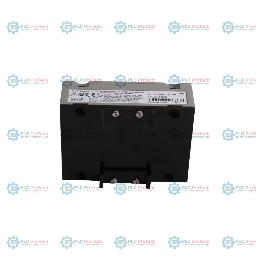
Environmental
Operating Temperature
-35 to +85 Celsius
Storage Temperature
-40 to +100 Celsius
Relative Humidity
100% condensing, non-submerged
Connections/Interfaces
Terminal / Connector
Function
PROX
Proximity Probe Input Terminal Connection
COM
Signal Common / System Ground
+4-20mA
Positive Loop Power / Current Output Terminal
-4-20mA
Negative Loop Power / Current Output Terminal
BNC
Dynamic Signal Output (Buffered Proximity Voltage)
Installation Guidelines
Dimensions and Mounting
The module accommodates both panel (bulkhead) and DIN rail mounting options. When using the panel mount configuration, prepare four mounting holes with a spacing layout of 69.9 mm by 63.5 mm. Use the standard 5.8 mm diameter mounting holes or the supplied 6-32 x 1.326 screws for secure bulkhead fixation. For DIN rail configurations, ensure a standard 35 mm DIN rail is rigidly installed before snapping on the transmitter's DIN mount clips.
Grounding and Shielding
Proper grounding is essential to minimize noise interference. The transmitter must be mounted to a grounded plate or a grounded DIN rail. Ensure the cable shield is grounded at only one end, typically at the control room/DCS side, to prevent ground loops.
Probe Gap Adjustment
Before final commissioning, the proximity probe must be physically positioned (gapped) relative to the shaft target. Adjust the gap until the transmitter output reads approximately 12 mA, which corresponds to the midpoint of the linear thrust range.
Cable Routing
Run probe and loop cables in dedicated, grounded metal conduits or cable trays. Avoid routing transmitter cables parallel to high-voltage AC power lines or heavy machinery switching circuits to prevent electro-magnetic interference (EMI).
Hazardous Area Precautions
When installed in classified areas, appropriate intrinsic safety barriers or explosion-proof housings must be utilized in accordance with local electrical codes and the specific installation drawings provided by the manufacturer.
FAQ
What is the primary function of this thrust transmitter?
It measures the axial displacement or thrust position of a rotating machine shaft relative to a fixed reference point using a non-contacting proximity probe.
What type of probe system is compatible with this transmitter?
It is designed specifically to interface with a Bently Nevada 3300 NSv proximity probe and extension cable system.
How is the device powered?
It is a loop-powered device operating on a 12 to 35 Vdc supply connected via the 4 to 20 mA current loop.
What does the BNC connector provide?
The BNC connector provides a buffered raw voltage signal proportional to the probe gap distance, allowing engineers to connect diagnostic equipment like oscilloscopes or analyzers without disconnecting the loop.
Can this device be used for radial vibration measurements?
No, this specific model is configured and calibrated for thrust (axial) position measurement. For radial vibration, a 990 Vibration Transmitter should be used.
What are the exact physical footprints required for panel mounting?
The footprint spacing required for the four mounting holes is 69.9 mm (2.75 in) lengthways by 63.5 mm (2.50 in) widthways, using holes with a diameter of 5.8 mm.
Maintenance data connects work orders, sensor signals, asset history, costs, and technician knowledge. Used well, it improves planning, reliability, predictive maintenance, spare-parts control, and...
This article explains how integrated electric actuators, such as SMC’s e-Actuator series, are transforming industrial motion control by replacing traditional pneumatic and hydraulic systems. It...
This article explains how PLC systems perform core mathematical operations such as addition, subtraction, multiplication, division, modulo, and exponentiation within industrial automation. It shows...
The article explains several advanced Boolean logic functions used in PLC programming beyond basic AND, OR, and NOT operations. It covers how tools like truth tables, multiplexers, pulse generators,...
Boolean logic is the foundation of every PLC program. From simple machine controls to complex industrial automation systems, logic gates determine how controllers respond to changing inputs and...
Industrial firewalls play a critical role in OT cybersecurity, protecting PLC, DCS, and SCADA networks through segmentation, ingress/egress control, and IDS/IPS integration aligned with IEC 62443...
Choosing a selection results in a full page refresh.