Product Overview
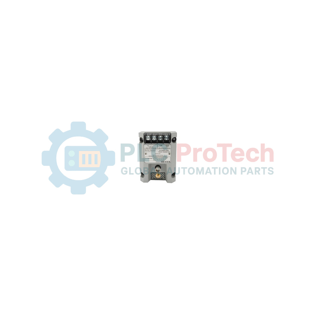
The 991-25-50-01-00 is a high-precision, loop-powered device engineered to provide a continuous 4-20 mA output proportional to axial shaft position. As a critical component of the Bently Nevada 991 series, this 991-25-50-01-00 transmitter is designed to integrate seamlessly with PLCs or DCS units for machinery protection without requiring a separate monitor rack. It is widely utilized in hydro-electric plants, reciprocating compressors, and industrial gearbox monitoring to detect thrust bearing wear and prevent rotor-to-stator contact. By delivering real-time axial displacement data, this transmitter enables predictive maintenance strategies that protect multi-million dollar assets from catastrophic failure, effectively reducing unplanned downtime and enhancing operational safety in demanding industrial environments.
Suffix Breakdown
The technical configuration of the 991-25-50-01-00 is defined by the following specific options:
-
25 (Full-scale Option): Configured for a measurement range of 25-0-25 mils (standard thrust range).
-
50 (System Length Option): Calibrated for use with a 5.0 meter (16.4 feet) total system length (probe plus extension cable).
-
01 (Mounting Option): Supplied with 35 mm DIN-rail clips for standardized cabinet installation.
-
00 (Agency Approval Option): Standard version; no specific hazardous area approvals required for the installation site.
Technical Specifications
| Attribute |
Specification Details |
| Model |
991-25-50-01-00 |
| Brand |
Bently Nevada (Baker Hughes) |
| Origin |
U.S.A. |
| Output Signal |
4-20 mA DC |
| Measurement Range |
25-0-25 mils |
| System Length |
5.0 meters |
| Mounting |
35 mm DIN-rail |
| Operating Temp |
-35 to +85 deg C |
| Supply Voltage |
12 to 35 VDC |
| Shipping Weight |
2.0 kg |
Operations & Maintenance FAQs
Can I use a 7.0-meter cable with this transmitter?
No. The 991-25-50-01-00 is specifically factory-calibrated for a 5.0-meter system length (Option 50). Using a different cable length will result in significant measurement errors and non-linearity in the 4-20 mA output.
What happens if the probe signal is lost?
The transmitter includes "Not-OK" status logic. If the input signal from the proximity probe falls outside the valid range (e.g., due to a broken cable), the 4-20 mA output will typically drop below 3.6 mA, allowing the control system to distinguish between a thrust alarm and a transducer failure.
Does this unit require a Proximitor?
No. The 991 series Thrust Transmitter combines the functions of a Proximitor and a signal conditioner into a single unit, providing a direct 4-20 mA interface for your PLC/DCS.
Engineering & Installation Guide
Axial Gap Calibration and Zeroing
When installing the 991-25-50-01-00, the proximity probe must be gapped while the shaft is in a known axial position (usually against the active thrust shoe). The transmitter is calibrated so that the center of the 4-20 mA range (12 mA) represents the "Zero" position. Ensure the probe is positioned within its linear range—typically indicated by a specific DC voltage at the "Prox Out" terminals—before finalizing the mechanical installation.
Wiring and Shielding Protocols
To ensure signal integrity in high-EMI industrial environments, use shielded twisted-pair cabling for the 4-20 mA loop. The shield should be terminated at the instrument ground of the control system (DCS/PLC) only. Avoid grounding the shield at both ends to prevent ground loops, which can cause signal drift or "ghost" alarms in the thrust readings.
Thermal Considerations and Enclosure
While the unit is rated for operation up to 85 deg C, localized heating inside control cabinets can exceed these limits. Ensure the DIN-rail mounting area has adequate ventilation. For installations in extremely corrosive or humid environments, the transmitter should be housed in a secondary NEMA 4X or IP66 rated enclosure to protect the terminal connections from oxidation.