Product Overview
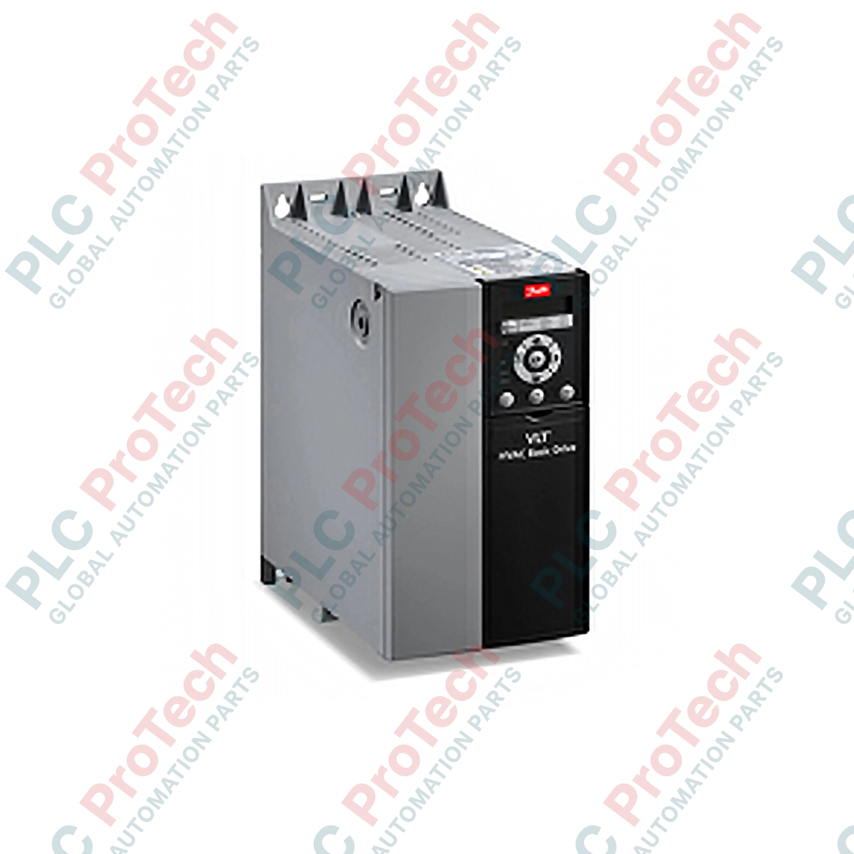
The Danfoss 131L9869 (FC-101P11KT4E20H4) is a VLT HVAC Basic Drive engineered specifically for controlling AC motors in heating, ventilation, and air conditioning systems. Rated at 11 kW (15 HP) with a 3-phase input of 380-480 VAC, this frequency converter optimizes fan and pump operations in commercial buildings, water treatment plants, and cooling towers. It integrates a DC reactor to mitigate harmonic distortion and an RFI Class A1 (C2) filter to ensure electromagnetic compatibility within sensitive electrical cabinets. The drive features an Automatic Energy Optimizer (AEO) that reduces power consumption by 3-5% immediately upon startup and up to 15-25% annually by adjusting voltage to match load requirements. Built with coated PCBs for resistance against humidity and corrosive atmospheres, the IP20 chassis allows for side-by-side mounting without derating, maximizing panel density. Its built-in Smart Logic Controller replaces external PLC logic for simple applications, reducing engineering time and component count while ensuring reliable climate control and process continuity.
Type Code Configuration Breakdown
The model code FC-101P11KT4E20H4 defines the specific hardware and feature set of this drive:
-
FC-101: Series identifier for the VLT HVAC Basic Drive, optimized for cost-effective fan and pump control.
-
P11K: Power rating specifying 11 kW (approximately 15 HP) continuous output.
-
T: Indicates 3-phase mains input supply.
-
4: Mains voltage range of 380 - 480 VAC (50/60 Hz).
-
E20: Enclosure type IP20 (Chassis mount, Frame size H4/H5 depending on voltage variant).
-
H4: Integrated RFI filter compliant with Class A1 (EN 61800-3Category C2), suitable for industrial and commercial environments without additional filtering.
Technical Specifications
|
Parameter
|
Specification
|
|
Model
|
131L9869 (FC-101P11KT4E20H4)
|
|
Brand
|
Danfoss
|
|
Origin
|
Denmark
|
|
Weight
|
7.9 kg
|
|
Dimensions
|
90 mm x 400 mm x 200 mm (W x H x D, approx. Frame H4/H5)
|
|
Operating Temp
|
-10 to 50 deg C (Derating applies above 40-45 deg C)
|
|
Input Voltage
|
3 x 380 - 480 VAC (+/- 10%)
|
|
Output Power
|
11 kW / 15 HP
|
|
Output Current
|
24.3 A nominal (approx)
|
|
Enclosure Rating
|
IP20
|
|
RFI Filter
|
Class A1 (C2) Integrated
|
|
Communication
|
Standard RS485 (Modbus RTU / BACnet MS/TP)
|
|
Efficiency
|
Up to 98%
|
|
Certifications
|
CE, UL, cUL, C-Tick, KC
|
FAQs
What is the primary advantage of the FC 101 series over general-purpose drives for HVAC?
The FC 101 series includes HVAC-specific firmware features as standard, such as a built-in PI controller for pressure or flow regulation, fire mode override (drives the fan to a preset speed regardless of command), sleep mode to stop the motor when demand is low, and multi-pump control logic. These features eliminate the need for external PID controllers or complex PLC programming for standard ventilation tasks.
Does this drive require an external RFI filter or line reactor?
No. The 131L9869 (H4 option) includes an integrated RFI filter meeting Class A1 (C2) standards, which is sufficient for most industrial and commercial installations. It also contains an integrated DC link reactor to reduce harmonic distortion and protect the input rectifier, removing the need for an external AC line reactor in standard applications.
Can I connect a standard analog thermostat directly to this drive?
Yes. The drive features two configurable analog inputs (0-10 V or 4-20 mA) on terminals 53 and 54. You can map a room temperature sensor or potentiometer directly to the speed reference, allowing standalone operation without a building management system (BMS) for simpler retrofits.
Is the Local Control Panel (LCP) included with this specific part number?
The base type code "FC-101P11KT4E20H4" typically ships without the graphical LCP (keypad/display) attached, though some regional packaging variations may include it. For local programming and monitoring, the LCP 11 or LCP 12 (Order No. 130B1100 / 130B1101) is usually ordered separately. The drive can be programmed via the RS485 port using the MCT 10 software regardless.
Panel Integration and Wiring Precautions
-
Grounding Scheme: Connect the PE (Protective Earth) terminal using a minimum 10 mm2 green/yellow conductor to the panel's grounding busbar. Ensure the mounting panel is conductive and clean (use star washers) to guarantee low-impedance grounding, which is critical for the integrated RFI filter performance and safety.
-
Cable Separation: Maintain a minimum distance of 200 mm between motor power cables (U/V/W) and control signal cables (analog/digital/RS485) to prevent induced noise. Cross cables at 90 degrees if paths must intersect. Always use shielded twisted pair cables for control wiring and connect the shield drain wire to the common ground terminal (e.g., terminal 20 or 39) at the drive end only, or both ends if specified by local EMC codes.
-
Fusing and Disconnect: Install a 3-pole circuit breaker or fused disconnect switch on the input (L1, L2, L3) rated for the drive's maximum current (approx. 32 A for 11 kW). The drive contains a non-replaceable input fuse, but an external disconnect is mandatory for lockout/tagout procedures during maintenance.
-
Ambient Clearance: Although side-by-side mounting is allowed, ensure a minimum clearance of 50 mm above the top vent and 100 mm below the bottom vent to facilitate unrestricted airflow for the cooling fan. If installing in a cabinet with a closed door, verify the cabinet fan extraction rate handles the drive's heat dissipation (approx. 150-200W losses at full load).