Product Overview
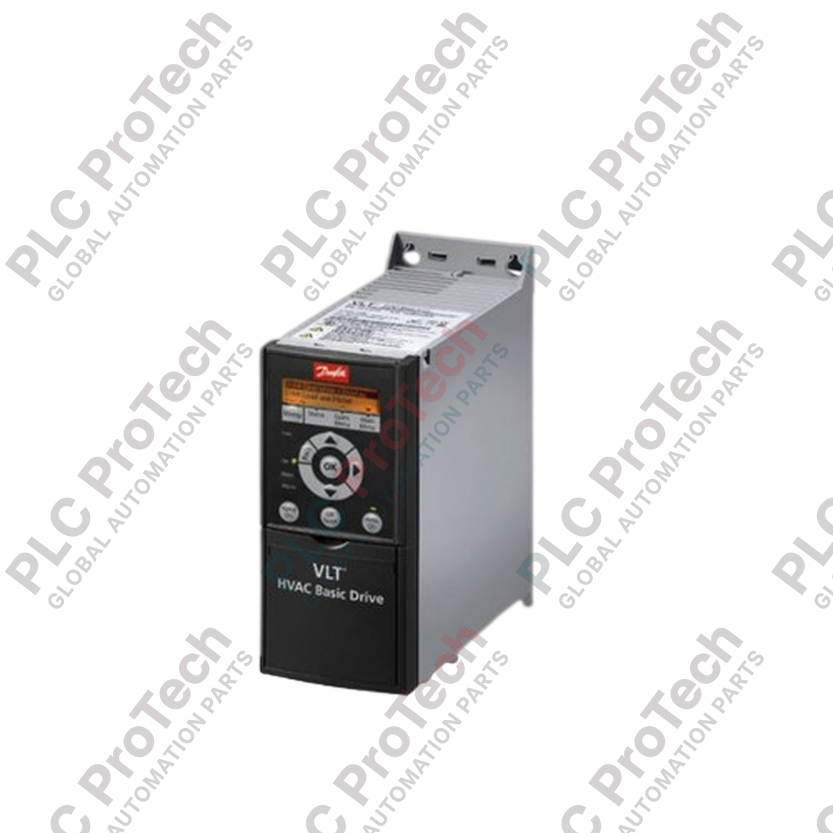
The FC-111P4K0T4 (FC111P4K0T4) is a high-efficiency variable speed controller designed specifically for HVAC infrastructure. Engineered for continuous operation in demanding environments such as power plants, water treatment facilities, and industrial complexes, this drive precisely regulates centrifugal pumps, fans, and air handling units. By aligning motor speed with real-time process demand, the unit eliminates inefficiencies associated with mechanical throttling. Integrating this drive into central control systems reduces grid strain, mitigates mechanical stress on couplings and belts, and prevents unscheduled downtime caused by hardware fatigue.
Technical Configuration
The internal architecture of this drive features robust power electronics designed for line stability under continuous load cycling. It includes built-in radio frequency interference (RFI) filters, meeting industrial emission standards without requiring external line conditioners. The proprietary H2 enclosure utilizes an isolated backplate airflow design, which channels heat away from sensitive control PCBs to prevent particulate accumulation and atmospheric corrosion. Furthermore, integrated electronic thermal overload mechanisms continuously monitor motor current, facilitating automatic tripping or current folding during phase loss or supply imbalances without the need for auxiliary external sensors.
Technical Specifications
| Feature |
Specification |
| Model |
FC-111P4K0T4 |
| Brand |
Danfoss |
| Typical Shaft Power |
4.0 kW (5.0 hp) |
| Protection Class |
IP20 (H2 Enclosure) |
| Continuous Output (40 deg C) |
9.0 A (380-440 V) / 8.2 A (441-480 V) |
| Max Input Current |
8.3 A (380-440 V) / 6.8 A (441-480 V) |
| Operating Temp |
-10 to 50 deg C |
| Max Wire Size |
4 mm squared (10 AWG) |
| Drive Efficiency |
98.0 % (Typical) |
| Weight |
3.4 kg |
FAQs
How does ambient thermal elevation affect drive output?
The drive operates at nominal specifications up to 40 deg C. At temperatures between 41 deg C and 50 deg C, internal de-rating logic automatically scales down the continuous current limits to prevent thermal degradation of the IGBT modules.
How does the drive handle fluctuations between 400 V and 480 V supply lines?
The internal microcontrollers support a 3x380-480 V input range. The drive automatically balances the maximum continuous output current—dropping from 9.0 A to 8.2 A—to maintain power dissipation within safe design thresholds.
What are the limitations regarding power cabling cross-sections?
The mains and motor terminals accept copper conductors up to a maximum size of 4 mm squared (10 AWG). Exceeding this wire size may cause permanent damage to the clamping assembly.
Field Commissioning & Safety Protocols
-
Thermal Clearances: Mount the H2 enclosure vertically on a solid, non-flammable back panel. Provide a minimum ventilation gap of 100 mm above and below the chassis to ensure unobstructed convective heat dissipation.
-
Shield Bonding: Terminate motor cable shields using 360-degree high-frequency ground clamps directly to the metallic mounting plate. Avoid using wire pigtails for shielding, as they introduce inductive spikes that can corrupt adjacent control signals.
-
Torque Requirements: Tighten all power connection terminals to a precise torque of 0.5 Nm. Failure to achieve this torque results in high-resistance paths, leading to terminal overheating during intermittent load peaks of up to 9.9 A.