High-Precision Motion Controller Overview
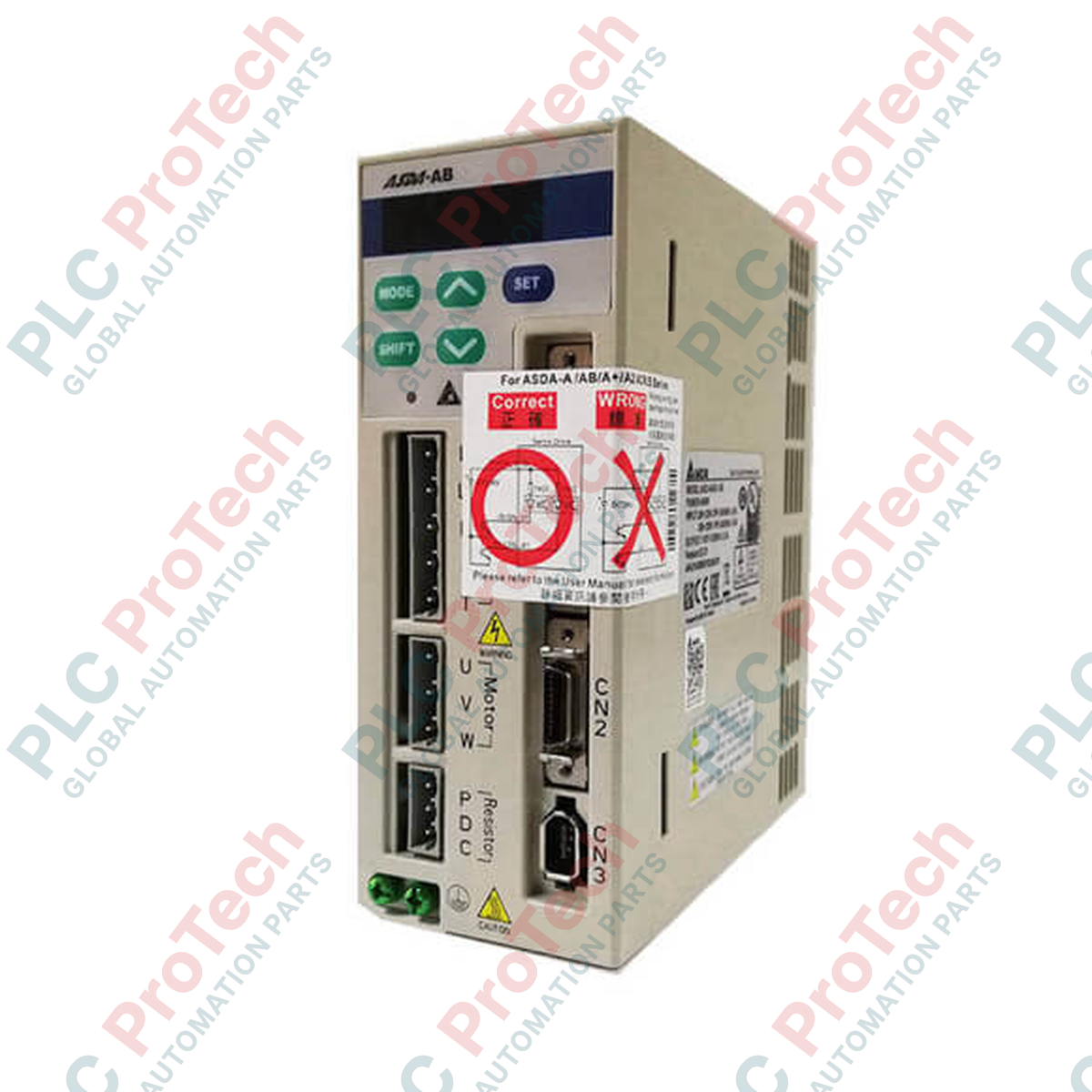
The ASD-A0121-AB (ASD-A0121-AB) is a compact, digital AC servo drive designed by Delta as part of the established ASDA-A series platform. Delivering 100 W of output power, this high-performance amplifier uses Space Vector Pulse Width Modulation (SVPWM) control to manage core motor dynamics with exceptional energy efficiency and minimal current ripple. Optimized for low-inertia, high-frequency positioning workflows—such as semiconductor wire bonding, small-scale medical pipetting systems, automated laboratory pick-and-place arms, and precise electronic assembly—the ASD-A0121-AB stabilizes axis timing and dramatically curtails unscheduled machinery downtime through advanced tracking logic and built-in dynamic braking. Its dual-mode command interface supports smooth transitions between real-time external signal streams and internally cached operational parameters.
Hardware Control Architecture & Command Processing
The internal processing layer of the ASDA-A 100W amplifier is engineered for highly responsive multi-protocol positioning execution:
-
SVPWM Main Circuit Control: Maximizes DC bus voltage utilization and reduces motor acoustic noise and harmonic thermal generation through specialized space-vector switching strategies.
-
Dual Smoothing Filters: Employs an adjustable combination of Low-pass and P-curve filters to round off sharp digital command transitions, protecting mechanical gearboxes against rapid torque shocks.
-
High-Resolution Feedback Decoding: Interfaces directly with 2500 ppr optical encoders, multiplying feedback internally to maintain a stable 10000 ppr closed-loop resolution baseline.
-
Built-in Dynamic Brake: Outfitted with an active internal dynamic braking circuit that automatically shorts the motor windings through power resistors during emergency stops, bringing the axis to an immediate, controlled halt.
Critical Engineering Parameters
The following detailed parameter table identifies the electrical, mechanical, and signal constraints verified for automation panel integration:
| Parameter |
Specifications |
| Model |
ASD-A0121-AB |
| Brand |
DELTA |
| Origin |
Taiwan |
| Drive Power Rating |
100 W |
| Modulation Protocol |
Space Vector Pulse Width Modulation (SVPWM) |
| Feedback Multiplier |
2500 ppr base / 10000 ppr quadrature resolution |
| Max Line Driver Pulse Frequency |
500 Kpps |
| Max Open Collector Pulse Frequency |
200 Kpps |
| Analog Speed Input Range |
0 to +/- 10 VDC (10K Ohm input impedance) |
| Speed Regulation Ratio |
1:5000 |
| Tuning Methodologies |
Real-time Auto-tuning / Step Manual override |
| Cooling Topology |
Natural Air Circulation (Fanless design) |
| Net Hardware Weight |
1.50 kg |
| Shipping Weight |
3.00 kg |
Technical Knowledge Base & Common Inquiries
What are the specific tracking frequency limits between Line Driver and Open Collector signal lines?
The digital command interface automatically shifts performance based on the hardware driver used. High-speed Line Driver inputs support differential frequencies up to 500 Kpps and offer superior common-mode noise rejection for long cable distances. Standard 24 VDC Open Collector lines are limited to a maximum threshold of 200 Kpps due to slower transistor fall times and capacitive signal distortion over extended distances.
How do the integrated Auto and Manual tuning modes balance machine inertia?
The Real-time Auto-tuning mode continuously calculates the load-to-motor inertia ratio by sampling velocity error waveforms during operation, automatically updating the position loop gain ($K_{pp}$) and speed loop gain ($K_{vp}$). For highly non-linear or flexible mechanical link setups, engineers can toggle to Manual mode to manually set inertia variables and adjust notch filter frequencies to dampen target structural resonance points.
Does the fanless cooling design impact panel orientation or density layouts?
Yes. Because the 100W drive relies entirely on natural air circulation rather than forced-air mechanical fans, it generates a unique thermal convection profile. Drive modules cannot be tightly packed against high-heat elements without dedicated air gaps, and the amplifier must be oriented straight up to allow hot air to naturally escape through the chassis venting.
Field Commissioning & Safety Guidelines
-
Fanless Mounting Clearance Buffers: Install the drive housing strictly in a vertical orientation onto a flat, non-combustible metallic sub-panel. Because this model utilizes natural air circulation for thermal management, maintain an open clearance safety zone of at least 40 mm on both sides and 100 mm above and below the chassis frame. Monitor the internal cabinet ambient air to ensure it remains within factory parameters.
-
Analog Input Shielding & Impedance Alignment: When commanding velocity or torque profiles via the 0 to +/- 10 VDC interface, route the command lines through continuous twisted-pair shielded instrumentation cables. Ground the braided shield exclusively at the drive chassis ground bar. Keep these low-voltage lines completely separated from high-frequency motor leads to protect the 10K Ohm input impedance matrix from high-frequency EMI noise corruption.
-
Encoder Line Grounding Protocol: Run dedicated, braided shielded cables for the feedback encoder loop. Ensure the connection back to the drive's CN2 port uses a robust, low-impedance connection at the connector shell. Never run encoder signal cables through the same wiring ducts as AC mains lines or VFD power outputs, as high-voltage cross-talk can drop pulse counts and trigger instant encoder communication faults.