Overview & Operational Value
The ASD-B1021-A (ASDB1021A) is an industrial AC servo drive designed for high-efficiency velocity, torque, and positioning applications within the legacy Delta ASDA-B platform. Engineering a robust 1 kW power output, this drive serves as a primary motion control component for automated machinery, including industrial CNC milling centers, textile winders, labeling equipment, and medium-duty material handling conveyors.
By utilizing optimized current loop control algorithms, the unit ensures stable mechanical torque delivery and rapid dynamic response times. This operational stability plays a critical role in minimizing mechanical overshoot, regulating tracking accuracy, and preventing costly production line stoppages caused by tracking errors under varying load conditions.
System Integration & Control Interface
Operating on a 220 V single-phase alternating current input, this drive integrates seamlessly into standard factory control panels without requiring complex three-phase power step-down transformers. As a standard 'A-Version' unit within the ASDA-B series, the hardware provides reliable, deterministic control via traditional external analog voltage commands or high-speed pulse train inputs.
The onboard interface features integrated digital inputs and outputs that can be mapped to handle critical hardware handshakes—such as servo-enable, reset, and fault-status signaling—directly with a supervisory PLC or standalone motion controller. Additionally, internal tuning parameters allow technical personnel to adjust gain curves to match the exact inertia ratio of the connected mechanical load.
Technical Performance Matrix
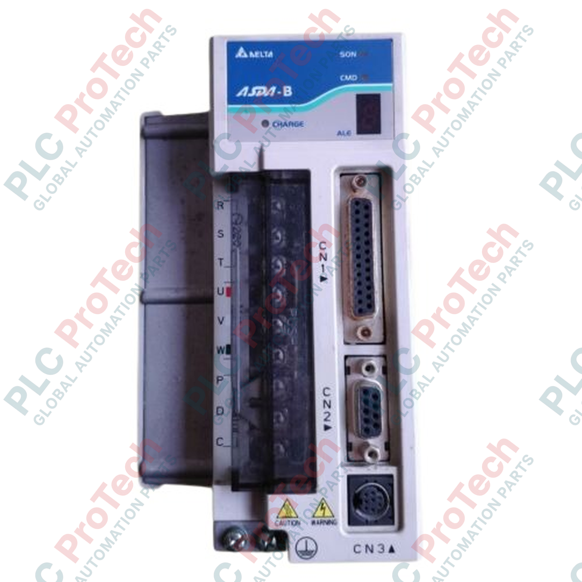
| Parameter |
Specification Details |
| Model |
ASD-B1021-A |
| Brand |
DELTA |
| Origin |
Taiwan |
| Drive Category |
AC Servo Drive |
| Series |
ASDA-B |
| Rated Output Power |
1 kW |
| Input Voltage / Phase |
220 VAC, 1-phase |
| Control Formats |
External Pulse Train / Analog Voltage |
| Hardware Version |
A |
| Cooling Mechanism |
Built-in forced-air cooling fan |
| Protective Attributes |
Overcurrent, Overvoltage, Overload, Regeneration Fault |
| Dimensions |
185 mm x 85 mm x 166 mm |
| Weight |
2.0 kg (Shipping Weight: 4.0 kg due to bulk industrial packaging) |
| Permissible Ambient Temp |
0 to 55 deg C |
Engineering Queries & Diagnostic Methods
-
What are the primary indicators of a DC bus overvoltage fault, and how is it resolved?
An overvoltage fault occurs when the internal DC bus voltage exceeds critical limits, typically during rapid deceleration of high-inertia loads. If the drive displays an overvoltage alarm code, verify the operation of the internal regenerative brake loop or install a properly rated external regenerative resistor across the designated power terminals to dissipate excess kinetic energy safely.
-
Can this single-phase drive handle high-duty-cycle continuous start/stop profiles?
Yes. However, continuous rapid cycling draws significant inrush currents through the single-phase rectifier bridge. To prevent premature thermal degradation of the internal input capacitors, monitor the drive’s thermal registers and ensure the cycle profile allows sufficient idle time or implement an external line reactor to smooth current peaks.
-
How is command signal noise diagnosed if the motor exhibits positioning drift?
Positioning drift or erratic shaft behavior during pulse train operations typically indicates electrical noise on the signal lines. Use an oscilloscope to inspect the differential pulse lines at the CN1 connector. If high-frequency voltage spikes are present, ensure that twisted-pair shielded cabling is used and that the drive chassis has a solid, low-impedance connection to the central factory ground.
Field Commissioning & Safety Protocols
Cabinet Grounding and Noise Suppression
To ensure stable microprocessor operation, connect the drive’s green ground terminal to the main subpanel backplate using a heavy-gauge copper wire (minimum 14 AWG). Strip away any paint beneath the mounting points to guarantee direct metal-to-metal contact. Install an isolation EMI filter on the 220 VAC input line to prevent high-frequency drive switching noise from propagating back into adjacent low-voltage sensor circuits.
Input Power Wiring and Circuit Protection
Wire the incoming 220 VAC single-phase lines to the main power terminals using appropriate industrial wire sizing. Install a fast-acting molded case circuit breaker (MCCB) or a set of semiconductor fuses upstream of the drive to protect the input rectifier bridge against sudden high-current short circuits. Never connect the incoming AC power lines directly to the motor output terminals U, V, and W, as this will immediately destroy the internal IGBT power stage.
Clearances and Airflow Path
Because this 1 kW drive relies on an internal forced-air fan for heat dissipation, maintain a minimum vertical clearance of 50 mm above and below the drive housing, and 10 mm of horizontal space from adjacent control components. Periodically inspect the cooling fan intakes for dust or oil accumulation, which restricts airflow and can cause the drive to trip on an overtemperature fault when operating at high torque outputs.