Description
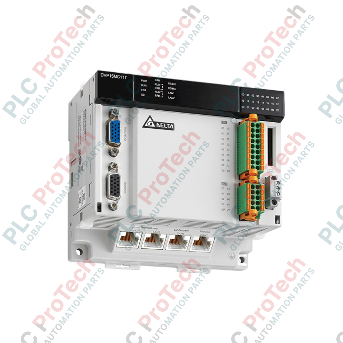
Managing complex multi-axis synchronized movement across high-speed industrial architectures, the Delta Electronics DVP15MC11T serves as a high-performance, EtherCAT-enabled motion controller. Engineered to control up to 24 virtual or real axes, this controller integrates robust networking protocols, including CANopen, Ethernet, and RS-485, directly into a compact DIN-rail form factor. Its architecture incorporates high-density local physical inputs and outputs, allowing microsecond-level response times for critical registration and positioning applications without requiring external interface cards.
Features
-
Multi-Axis EtherCAT Bus: Directly controls and synchronizes up to 24 axes (including virtual axes) with high-speed transmission.
-
Comprehensive On-Board I/O: Built-in 16 high-speed digital input channels and 8 transistor (N-MOS/Sink) output channels.
-
Multi-Protocol Communication: Standard integration of Ethernet, CANopen (Master/Slave), and RS-485 ports for flexible factory network deployment.
-
Standardized Programming: Supports PLCopen motion control function blocks for simplified multi-axis programming, electronic cam (E-Cam) curves, and gearing configurations.
-
Modular Expansion: Compatible with standard left-side and right-side DVP series modules for expanded analog, digital, or specialized network interfaces.
Applications
-
Packaging and Labeling: Synchronized rotary cutters, flying shears, and continuous flow wrappers.
-
Textile Machinery: Precise tension control, winders, and multi-axis weaving systems.
-
Material Handling: Multi-axis gantry robots, automated sorting stations, and high-speed pick-and-place systems.
-
Electronic Manufacturing: Assembly machines, solder-paste printers, and component placement lines.
Technical Specifications
| Parameter |
Specification |
| Manufacturer |
Delta Electronics |
| Model Number |
DVP15MC11T |
| Product Type |
Multi-axis Motion Controller |
| Input Power Voltage |
24 VDC (-15% to +20%) |
| Power Consumption |
8 W Max. |
| Isolation Voltage |
500 VDC (Secondary-PE) |
| Fuse Capacity |
3 A / 30 VDC, Polyswitch |
| Digital Inputs |
16 channels (High-speed, sink/source compatible) |
| Digital Outputs |
8 channels (Transistor, N-MOS/Sink) |
| Integrated Communication |
EtherCAT, Ethernet, CANopen, RS-485 |
| Weight |
0.425 kg |
| Shipping Weight (Calculated) |
1.500 kg |
Connections and Interfaces
| Connector / Interface |
Function / Circuit Assignment |
| EtherCAT Port |
Dedicated RJ45 interface for high-speed synchronization of servo drives. |
| Ethernet Port |
RJ45 interface supporting Modbus TCP client/server and program upload/download. |
| CANopen Port |
5-pin terminal block for system expandability and CANopen master/slave protocols. |
| COM Port (RS-485) |
Modbus RTU/ASCII communication for HMIs and auxiliary variable frequency drives. |
| High-Density I/O Header |
Spring-clamp connection system for 16 DI and 8 DO pins, reducing field wiring time. |
Empirical Engineering Insights
Alternative Models & Compatibility
The DVP15MC11T represents a significant upgrade over legacy DVP-MC series units using CANopen alone. While drop-in code migration is possible via ISPSoft, developers transitioning from CANopen-only structures must adjust network cycle times to accommodate the significantly faster processing capabilities of the EtherCAT physical layer. Verify that your downstream servo drives support CoE (CAN Application Protocol over EtherCAT) for full feature operability.
Application Pitfalls & Engineering Notes
EtherCAT network stability is highly sensitive to electromagnetic interference (EMI). When routing high-voltage motor cables alongside communication lines, always use SF/UTP double-shielded copper cabling. Avoid running EtherCAT lines parallel to VFD output cables in standard wireways to prevent cyclic frame loss, which can cause the controller to register synchronization faults and enter a safe-state shutdown.
Commissioning & Wiring Tips
When utilizing the built-in high-speed digital inputs for registration mark sensing, ensure the inputs are wired with a short, shielded cable run. Shielding must be terminated to ground only at the panel backplate to eliminate ground loop current. To guarantee deterministic response, always map these specific physical inputs to higher-priority interrupt tasks in ISPSoft, keeping them separate from the main PLC program cycle.
Installation Guidelines
CRITICAL WARNING: ELECTRICAL SHOCK AND UNCOMMANDED MOTION HAZARD
Isolate all physical power sources prior to mounting, wiring, or servicing the unit. Ensure the 24 VDC supply is fully de-energized. Confirm that all downstream servo motor shafts are secure and isolated from active mechanical loads to prevent hazardous, uncommanded kinetic energy discharge during initial communications handshakes.
1
Mount the controller vertically onto a standard 35mm DIN rail. Ensure a minimum spacing clearance of 50mm above and below the device to permit adequate natural thermal convection within the enclosure.
2
Connect a heavy-duty copper grounding conductor from the PE terminal directly to the central panel ground busbar to establish high-frequency noise immunity.
3
Terminate the 24 VDC class-2 source wires into the power supply terminal block, taking strict care to verify terminal polarities (positive and negative) before securing.
4
Insert the RJ45 EtherCAT network line into the designated port, ensuring it latches with an audible click, and route the line in a dedicated low-voltage cable tray.