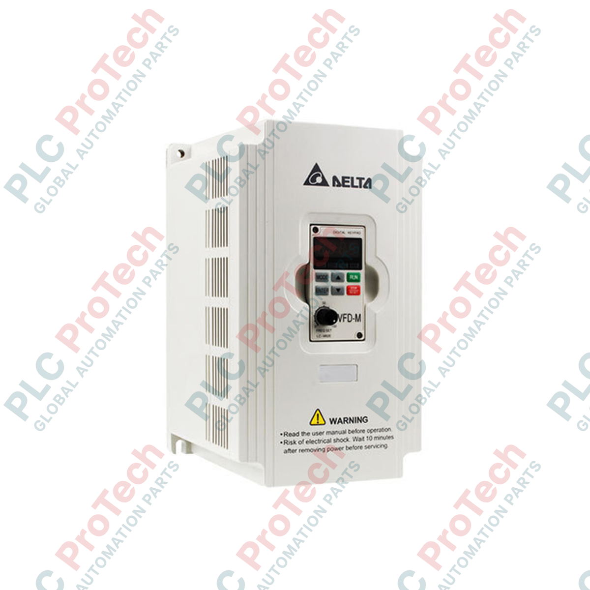
Description
Engineered for high-precision speed and torque regulation in compact industrial systems, the Delta Electronics VFD055M21A micro drive provides versatile sensorless vector control within the reliable VFD-M Series framework. This module delivers robust control characteristics and features built-in Modbus serial communications for seamless integration into distributed control networks. Featuring a highly efficient heat-dissipation design and a user-friendly programming interface, this drive balances heavy-duty performance with a compact physical footprint, making it ideal for automated manufacturing lines, fan networks, and conveying equipment.
Features
-
Advanced Control Algorithms: Features dual sensorless vector and adjustable V/F curve profiles for high starting torque and precise velocity control.
-
Broad Carrier Frequency Range: Adjustable carrier frequency from 1 to 15 kHz to minimize acoustic motor noise and optimize system efficiency.
-
Integrated Communication: Built-in RS-485 communication port supporting standard Modbus RTU/ASCII protocols for clean system integration.
-
Dynamic Braking: Built-in braking chopper allows direct connection of an external braking resistor for rapid deceleration and stopping.
-
Automated Tuning: Features intelligent auto-tuning capabilities to match motor winding parameters for optimal torque delivery.
Applications
- High-speed packaging and filling machinery requiring rapid acceleration/deceleration.
- Conveyor and material handling systems with varying payload demands.
- Industrial fan systems and centrifugal pump operations.
- Precision woodworking equipment and small machine tool spindles.
Technical Specifications
| Manufacturer |
Delta Electronics |
| Model Number |
VFD055M21A |
| Series |
VFD-M Series |
| Rated Output Capacity |
3.8 kVA |
| Rated Output Current |
10 A |
| Maximum Output Voltage |
3-phase, proportional to input voltage |
| Output Frequency Range |
0.1 to 400 Hz |
| Carrier Frequency |
1 to 15 kHz |
| Rated Input Power Supply |
Single-phase / 3-phase, 200 to 240 VAC, 50/60 Hz |
| Input Voltage Tolerance |
+/- 10% (180 to 264 VAC) |
| Input Frequency Tolerance |
+/- 5% (47 to 63 Hz) |
| Cooling Method |
Forced Fan Cooling |
| Net Weight |
3.2 kg |
| Shipping Weight (Calculated) |
5.0 kg |
Empirical Engineering Insights
Alternative Models & Compatibility
The VFD055M21A is standard within the VFD-M series legacy portfolio. When substituting this unit, closely match the input phase configurations. While this unit can accept both single-phase and three-phase 230V power inputs, utilizing single-phase power requires careful sizing verification of downstream branch protection circuit breakers to handle the higher input line currents (up to 27 A in single-phase applications under high load conditions).
Application Pitfalls & Engineering Notes
Single-phase incoming power subjects the internal DC link bus capacitors to elevated thermal stress and increased ripple current. Ensure that the drive is operated strictly within the rated 10 A continuous output threshold when powered via a single-phase supply. Maintain side clearances of at least 50 mm when panel-mounting multiple drives in close proximity to prevent hot spots from triggering an over-temperature fault (oH).
Commissioning & Wiring Tips
Always route the control signal wires (AVI, ACI, and digital control terminals) through a dedicated, shielded conduit separate from the high-power AC supply input (R, S, T) and motor output (U, V, W) lines. Ensure that control common (GND) is not bonded directly to the frame earth ground; the physical chassis earth terminal must be connected to a dedicated, low-impedance ground point (under 100 ohms) to avoid high-frequency noise interference on analog inputs.
Installation Guidelines
CRITICAL SAFETY WARNING: De-energize all incoming power lines prior to opening the drive wiring cover. After disconnecting supply power, wait a minimum of 10 minutes to allow the DC bus capacitors to fully discharge. Use a reliable digital multimeter to verify that DC voltage between the + and - terminals is under 36 VDC before initiating any installation, terminal tightening, or wiring procedures.
1
Mount the VFD055M21A drive vertically to a flat, non-flammable backplate within a dust-free, dry enclosure, ensuring adequate clearance above and below for standard convective airflow.
2
Connect the single-phase (or three-phase) AC input power lines exclusively to terminals R and S (or R, S, T). Never apply mains voltage to the motor terminals U, V, or W, as this will result in immediate and catastrophic module damage.
3
Route shielded, low-capacitance motor cabling between terminals U, V, W and the motor stator terminals. Ensure both the motor frame and the drive ground terminal are securely bonded to a unified system ground bus.
4
Verify that all control loop terminations (e.g., potentiometer connections or Modbus communication wires) are secure, replace the cover plate, power up the system, and perform an initial motor auto-tune sequence before applying operational mechanical loads.