Overview & Operational Value
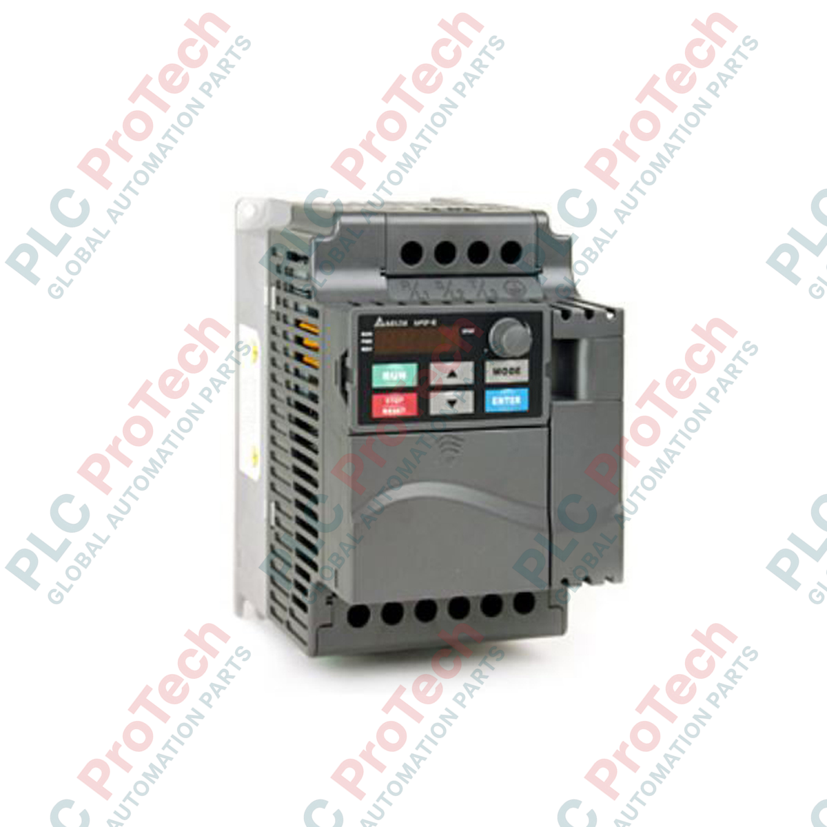
The VFD037E43T (VFD037E43T) is a modular, sensorless vector AC inverter drive engineered for high-efficiency speed and torque regulation of three-phase induction motors. Rated for a 5 HP (3.7 kW) motor capacity, this precision variable frequency drive is widely deployed across critical industrial applications, including commercial HVAC blower systems, centrifugal water pumps, automated conveyor lines, and material handling cranes.
By executing real-time flux vector calculations, the drive maximizes low-speed output torque while maintaining high speed stability. This dynamic regulation optimizes power consumption, prevents motor insulation breakdown caused by voltage spikes, and ensures uninterrupted throughput across continuous manufacturing processes.
Architecture & Hardware Configuration
Operating on a 460 V three-phase grid, this VFD-E Series unit features a modular hardware architecture that supports flexible side-by-side DIN-rail mounting to optimize enclosure layout efficiency. The "T" specification signifies a Frame A chassis layout equipped with an integrated internal brake chopper circuit.
This embedded chopper allows technical personnel to wire a dynamic braking resistor directly to the power terminals, enabling the drive to manage high-inertia deceleration ramps without experiencing overvoltage faults. The unit incorporates a removable keypad, an easily accessible cooling fan, and standard RS-485 Modbus RTU communication interfaces for seamless integration into industrial fieldbus networks.
Technical Performance Matrix
| Parameter |
Specification Details |
| Model |
VFD037E43T |
| Brand |
DELTA |
| Origin |
Taiwan |
| Drive Category |
Variable Frequency Drive (VFD) |
| Series Platform |
VFD-E |
| Applicable Motor Capacity |
3.7 kW (5 HP) |
| Mains Input Voltage |
460 VAC, 3-phase (50/60 Hz) |
| Output Frequency Range |
0.1 to 600 Hz |
| Control Method |
V/f Control, Sensorless Vector Control (SVC) |
| Chassis Framework |
Frame A, Built-in Brake Chopper |
| Communication Interface |
RS-485 (Modbus RTU) |
| Enclosure Protection |
IP20 |
| Dimensions |
142 mm x 72 mm x 152 mm |
| Weight |
1.9 kg (Shipping Weight: 3.5 kg with reinforced packaging) |
| Ambient Temperature Limit |
-10 to +50 deg C (Non-condensing) |
Engineering Queries & Diagnostic Methods
-
What parameter configurations are necessary to activate the integrated brake chopper?
The internal hardware chopper triggers automatically when the DC bus voltage exceeds the pre-set braking threshold. However, you must enable dynamic braking in the drive's parameter architecture (typically via parameter group 01) and define the maximum allowable braking duty cycle to prevent thermal overloading of the external resistor matrix.
-
How is the sensorless vector control mode calibrated for a generic 3.7 kW motor?
To achieve optimal torque response, decouple the motor shaft from the mechanical load and execute a dynamic auto-tuning routine. Input the motor's nameplate parameters—including rated voltage, frequency, base current, and rated speed—into the drive memory. The VFD will measure stator resistance and mutual inductance to optimize its internal vector control loop.
-
What corrective actions are required if the drive continuously trips on an Overcurrent (OC) fault during startup?
An overcurrent fault during acceleration indicates that the programmed acceleration ramp time is too short for the inertia of the load, or the V/f torque boost curve is set too high. Increase the acceleration time parameter, inspect the motor windings for phase-to-phase insulation breakages, and verify that the mechanical load turns freely without binding.
Field Commissioning & Safety Protocols
Power Circuit Protection and Wiring Architecture
Connect the 460 VAC incoming three-phase utility lines exclusively to terminals R, S, and T. Connecting incoming line power to output terminals U, V, and W will cause instantaneous catastrophic failure of the internal insulated-gate bipolar transistors (IGBTs). Install a properly sized three-phase molded case circuit breaker (MCCB) upstream of the drive to provide high-capacity thermal and magnetic short-circuit protection.
Braking Resistor Deployment and Safe Thermal Routing
When installing an external dynamic braking resistor across the B1 and B2 terminals, ensure the resistor assembly is mounted in a vertical metal housing separate from the primary control enclosure. Dynamic braking elements generate substantial thermal dissipation during cyclic deceleration; routing these units away from the drive prevents the rising hot air from artificially raising the VFD intake temperature above its 50 deg C ambient limit.
Control Signal Isolation and Grounding Procedures
Run all low-voltage control lines—such as 0-10 V analog speed references or 24 VDC digital start/stop commands—in a separate wiring tray away from the motor power leads. Use double-shielded twisted-pair (STP) cabling for all analog signals. Terminate the cable shield to the designated control ground terminal on the drive side only, leaving the field side floating to avoid creating ground loops that degrade speed reference tracking.