Overview & Operational Value
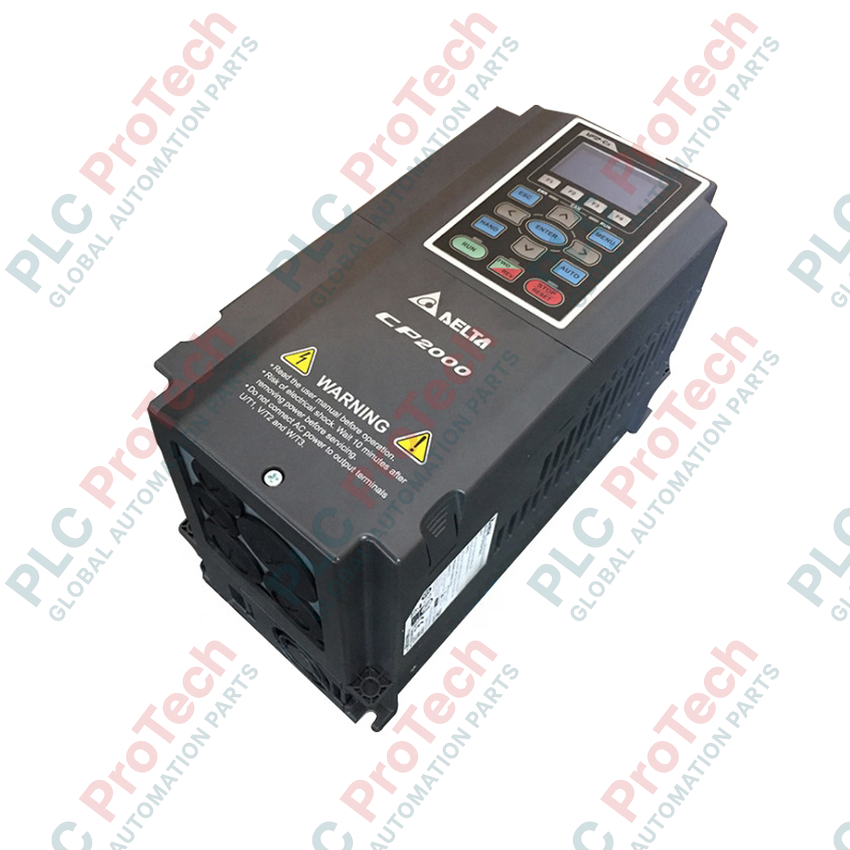
The VFD110CP43B-21 (VFD110CP43B21) is an industrial-grade variable frequency drive engineered specifically for centrifugal fan and pump applications within the Delta CP2000 automation framework. Delivering a 15 HP (11 kW) output capacity with a 24 Amps continuous current rating, this vector control drive targets energy conservation and advanced process regulation in municipal water treatment, commercial HVAC networks, cooling tower management, and large-scale agricultural irrigation.
By integrating dedicated pump control software macro structures alongside multi-motor synchronous cascading capabilities, the unit optimizes energy consumption profiles under variable load conditions. This specialized operation minimizes water hammer stresses in fluid networks, protects motor insulation from thermal breakdown, and dramatically reduces mechanical wear on impellers, bearings, and coupling components.
System Architecture & Environmental Construction
Operating on a 460 V three-phase power infrastructure, this CP2000 series drive incorporates advanced sensorless vector control (SVC) calibrated for variable torque loads, matching the exact power curves of fluid-displacement machinery. The hardware configuration features an installation architecture designed for wall mounting, allowing efficient cabinet layout deployment or direct-to-wall mounting where permissible.
The physical enclosure features a dual-rated IP20 and NEMA 1 protection barrier, shielding the internal microprocessor control cards, power bus capacitors, and gate-drive circuits from falling debris and accidental manual contact. The drive also integrates an intelligent multi-pump architecture capable of controlling up to eight auxiliary motors via relay outputs, balancing runtime hours to prevent uneven machinery degradation.
Technical Performance Matrix
| Parameter |
Specification Details |
| Model |
VFD110CP43B-21 |
| Brand |
DELTA |
| Origin |
Taiwan |
| Drive Category |
Sensorless Vector Control Drive (Fan/Pump Optimized) |
| Series Platform |
CP2000 |
| Applicable Motor Capacity |
11 kW (15 HP) |
| Rated Output Current |
24 Amps |
| Mains Input Power |
460 VAC, 3-phase (50/60 Hz) |
| Output Frequency Spectrum |
0.1 to 600 Hz |
| Enclosure Protection Standards |
IP20 / NEMA 1 |
| Mechanical Installation Type |
Wall Mount / Panel Backplate Mount |
| Built-in Network Logic |
BACnet, RS-485 Modbus RTU / ASCII |
| Physical Dimensions |
190 mm (W) x 320 mm (H) x 190 mm (D) / 7.48 in x 12.60 in x 7.48 in |
| Weight |
7.0 kg (Shipping Weight: 8.0 kg wrapped for distribution) |
| Permissible Ambient Temperature |
-10 to +50 deg C (De-rate above 40 deg C for side-by-side mounting) |
Engineering Queries & Diagnostic Methods
-
How is the integrated multi-pump synchronous cascade sequence configured?
The configuration is established via the specialized pump parameter group (typically Group 12). Technical personnel define the control master parameters, set the pressure feedback sensor scaling via the analog inputs, and map the internal auxiliary relay flags to cycle slave contactors sequentially based on PID demand or total accumulated run hours.
-
What adjustments optimize the energy-saving tracking curve on this drive?
Switch the V/f curve selection parameter from a linear output profile to an adjustable squared or cubed curve profile (Variable Torque Mode). This profile mirrors the natural physics of fan and pump loads, restricting the voltage supply at lower operating frequencies to achieve a massive reduction in continuous kilowatt-hour consumption.
-
What corrective loops resolve a PID Sleep/Wake error where the motor refuses to ramp down?
This behavior indicates that the sleep threshold frequency is set below the minimum frequency required to maintain physical check-valve seating, or the PID feedback loop gains are uncalibrated. Adjust the sleep detection delay timers, raise the minimum operating sleep frequency, and verify the physical feedback tracking of the transducible sensor via the drive's monitoring keypad.
Field Commissioning & Safety Protocols
High-Voltage Power Allocation and Upstream Fusing
Connect the incoming 460 VAC line power strictly to input terminals R, S, and T. Connecting incoming line power directly to motor terminals U, V, and W will cause instant thermal destruction of the internal IGBT output transistors. Install a high-interrupting capacity molded case circuit breaker (MCCB) or fast-acting semiconductor fuses upstream of the drive to isolate the unit against high-current line-side transients.
PID Sensor Integration and Low-Voltage Cable Isolation
Route all 4-20 mA or 0-10 V external pressure transducer feedback lines in a separate, isolated wiring track away from the main motor output leads. Use twisted-pair shielded instrumentation cabling (minimum 0.5 mm sq) for the feedback loop. Terminate the cable shield to the designated control ground pin on the drive side only, leaving the transducer end ungrounded to prevent ground loops from injecting noise into the PID algorithm.
Enclosure Ventilation and Spatial Clearances
When wall-mounting the drive inside a dust-prone industrial pump house, maintain a minimum vertical clearance of 100 mm above and below the cooling fins, and 50 mm of horizontal space from adjacent equipment. Ensure that the internal forced-air cooling fan path remains completely free of obstructions. In high-ambient environments approaching 50 deg C, install an active cabinet exhaust fan to evacuate localized thermal output and prevent the drive from tripping on a heat sink overtemperature fault.