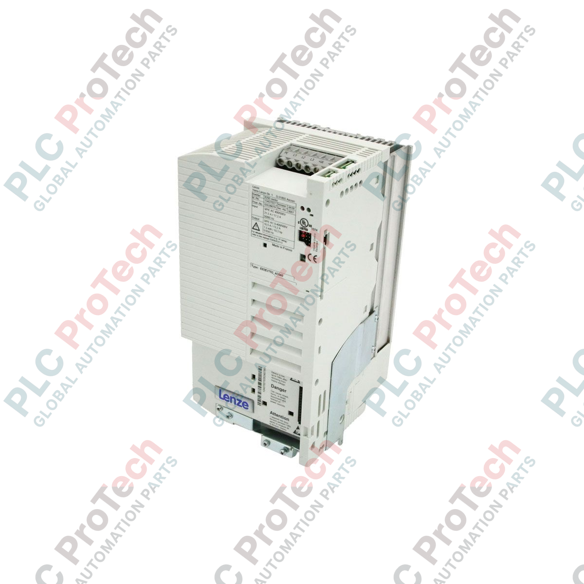
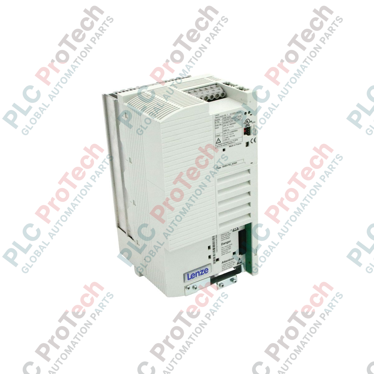
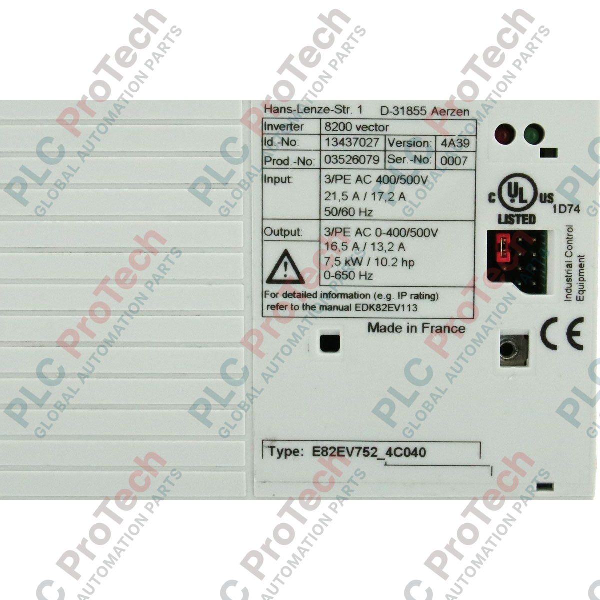
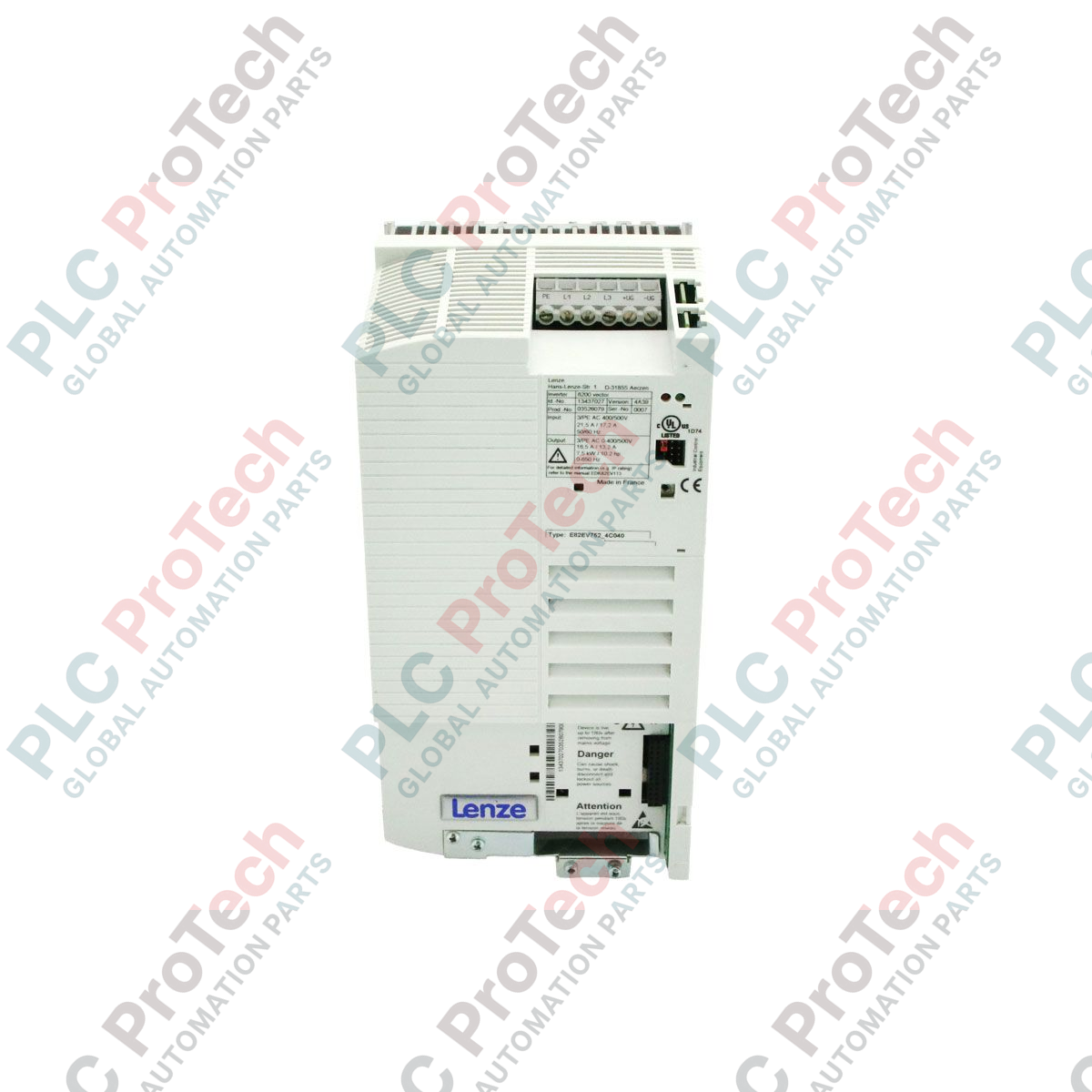
Engineered for precise speed and torque regulation of three-phase asynchronous motors, the Lenze E82EV752_4C040 frequency inverter serves as a core control component within the 8200 Vector series. This modular drive is designed to optimize energy consumption and mechanical wear across diverse industrial drive architectures, offering robust performance under varying load conditions.
Key Features
-
High-Performance Vector Control: Delivers exceptional dynamic response and high torque output even at low rotational speeds.
-
Modular Interface Architecture: Supports plug-in communication modules for seamless integration into standard fieldbus networks.
-
Integrated Interference Suppression: Built-in filters comply with standard industrial electromagnetic compatibility (EMC) requirements.
-
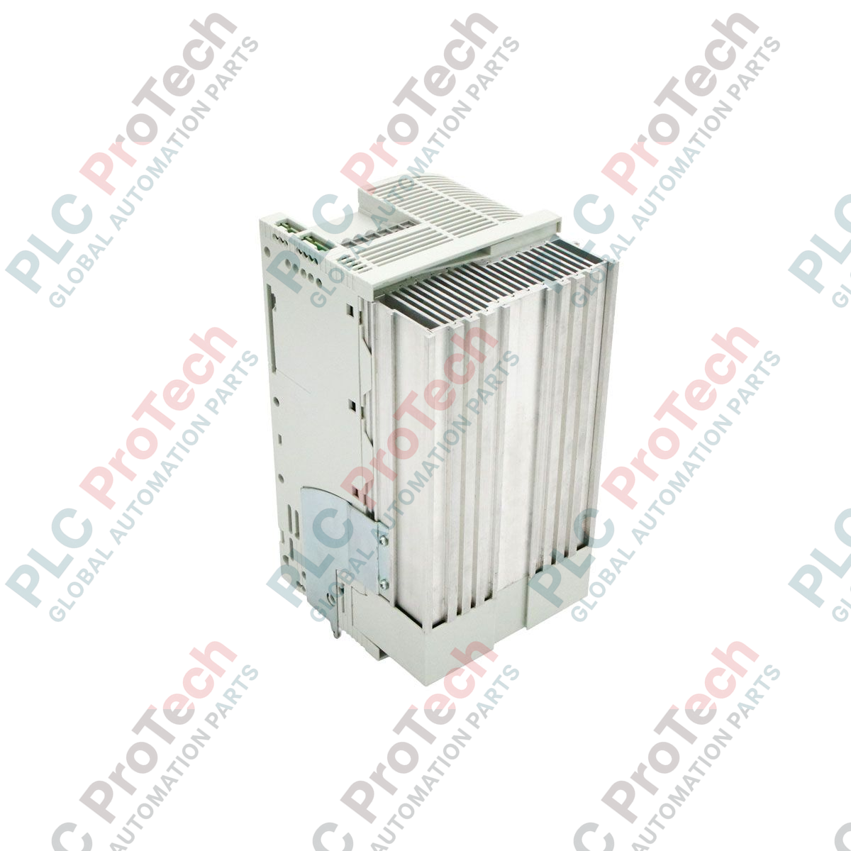
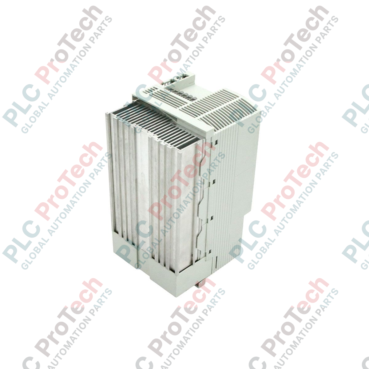
Thermal Management: Advanced heatsink design ensures reliable heat dissipation under continuous duty cycles.
Typical Applications
- Conveyor and material handling systems requiring controlled acceleration and deceleration.
- Centrifugal pumps and industrial ventilation fans utilizing variable flow control.
- Packaging machinery and processing lines requiring synchronized speed matching.
Technical Specifications
| Parameter |
Specification Value |
| Manufacturer |
Lenze |
| Model Code |
E82EV752_4C040 (E82EV752K4C040) |
| Product Series |
8200 Vector |
| Rated Power Output |
7.5 kW |
| Input Voltage Range |
3-Phase 400V to 500V AC |
| Product Phase |
Phase-Out (Legacy Support Available) |
| Commodity Code |
85044090 |
| Export Control Classification (ECCN) |
N |
| Country of Origin |
Germany |
| Shipping Weight (Calculated) |
3.82 kg |
| Package Dimensions (Calculated) |
15.00 x 6.00 x 10.00 cm |
Empirical Engineering Insights
Alternative Models & Compatibility
The E82EV752_4C040 is fully compatible with other 8200 Vector drives of the same frame size. When replacing legacy units, ensure that the plug-in function module (such as the standard I/O module or fieldbus interface card) is transferred to the new drive, as base units are shipped without control terminals.
Application Pitfalls & Engineering Notes
In enclosed control cabinets, this 7.5 kW unit generates significant thermal dissipation. Maintain a minimum vertical clearance of 100 mm above and below the chassis to prevent overtemperature faults (fault code OH). If operating continuously at 500V AC, verify that the motor insulation class is rated for high-peak voltage reflections.
Commissioning & Wiring Tips
Always utilize low-capacitance, shielded motor cables. The shield must be grounded with a large surface area contact directly at the drive's functional earth plate to prevent high-frequency leakage currents from disrupting nearby analog instrumentation.
Installation Guidelines
CRITICAL WARNING
Isolate all electrical power sources before commencing installation. Wait a minimum of 5 minutes after complete de-energization to allow the internal DC-bus capacitors to discharge to safe voltage levels (< 50 VDC) before touching terminals.
1
Mount the drive vertically on a flat, vibration-free backplate inside an IP54 or higher rated enclosure.
2
Connect the protective earth (PE) conductor to the designated grounding terminal block.
3
Wire the 3-phase AC mains supply to terminals L1, L2, and L3 using appropriate branch circuit protection.
4
Connect the shielded motor cable to terminals U, V, and W, ensuring the shield is grounded at both ends.
5
Insert the required communication or standard I/O module into the front interface slot prior to powering up.