Product Overview
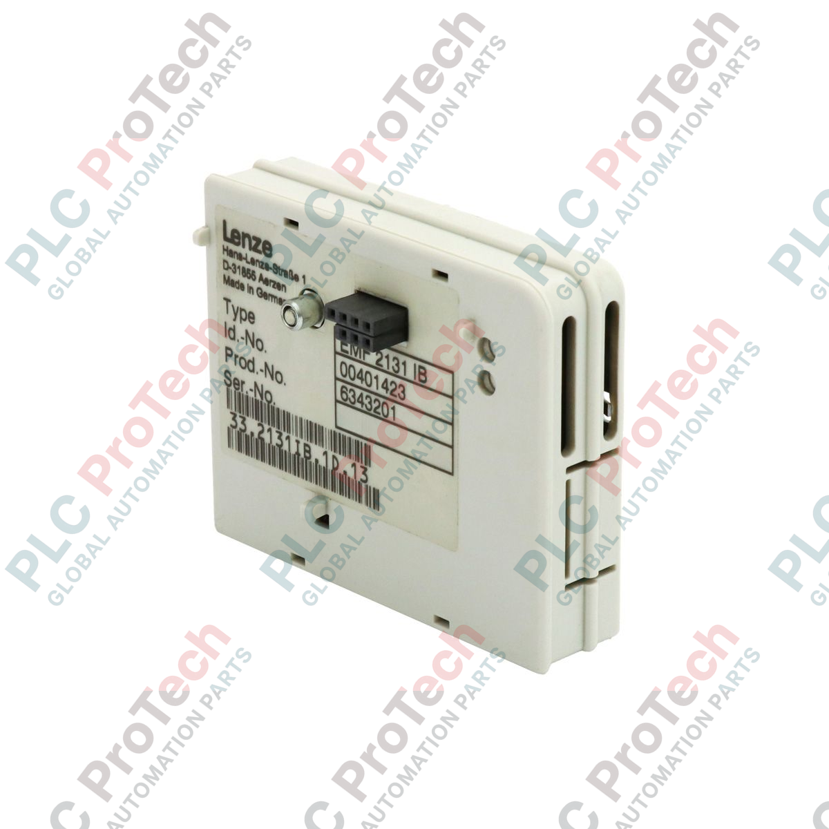
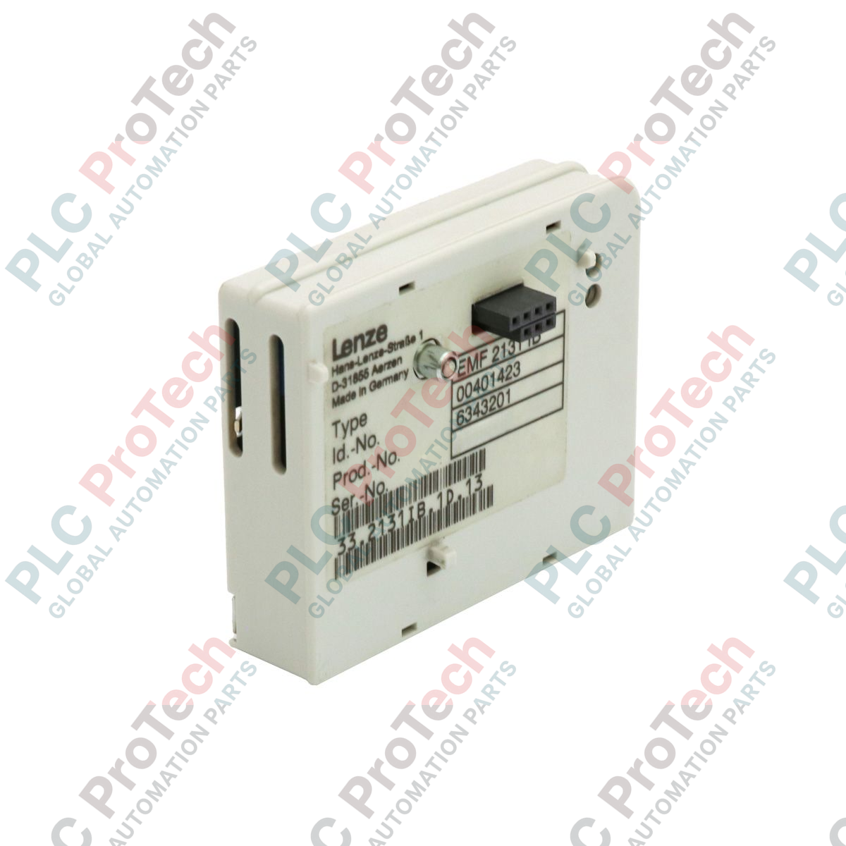
The EMF2131IB (EMF2131IB) is a high-speed PROFIBUS DP interface module specifically designed for the Lenze 8200-series and 8200 motec frequency inverters. This pluggable module enables the integration of decentralized drive technology into standardized fieldbus environments, allowing for real-time control and monitoring via a master PLC (such as a Siemens S7 or similar system). By providing a digital bridge for parameterization and process data exchange, the EMF2131IB eliminates the need for extensive analog wiring, thereby reducing electrical noise interference and commissioning time. As a specialized communication bridge, it is essential for complex automation architectures in automotive assembly, food processing, and high-speed logistics where synchronized drive coordination is critical.
Technical Configuration
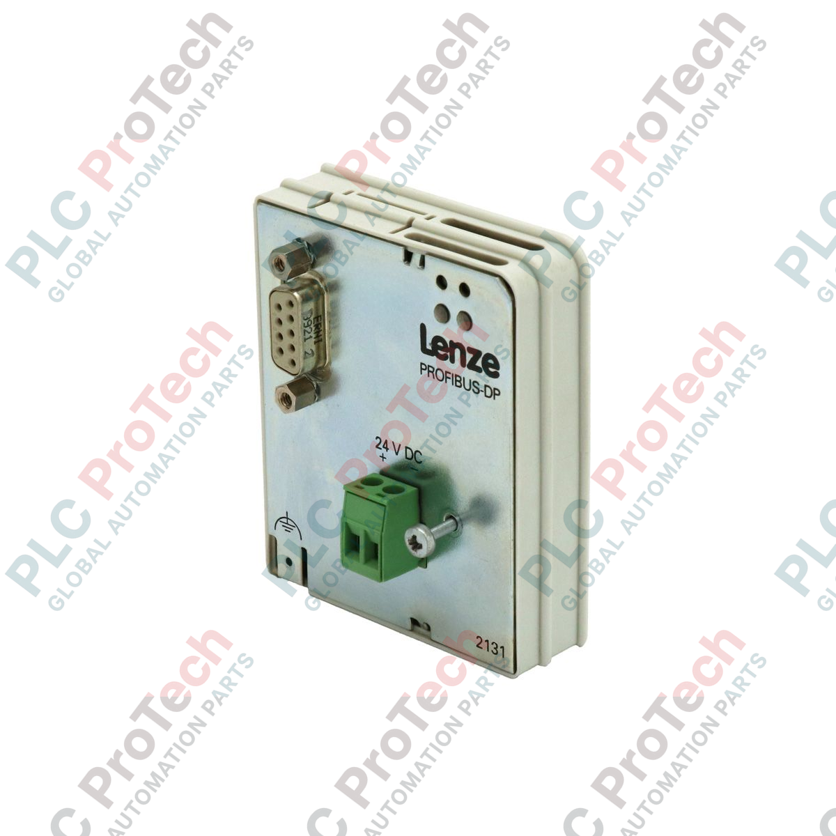
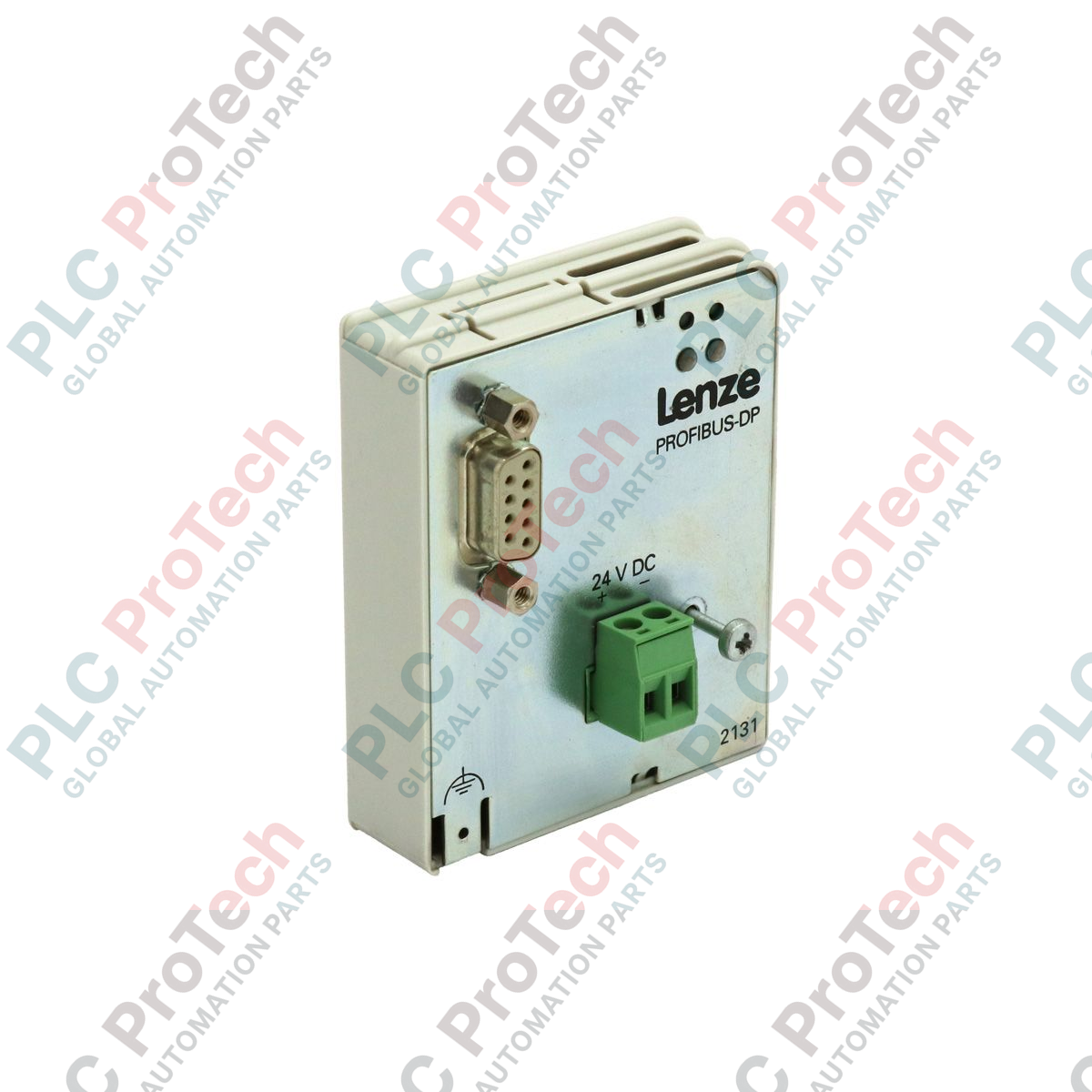
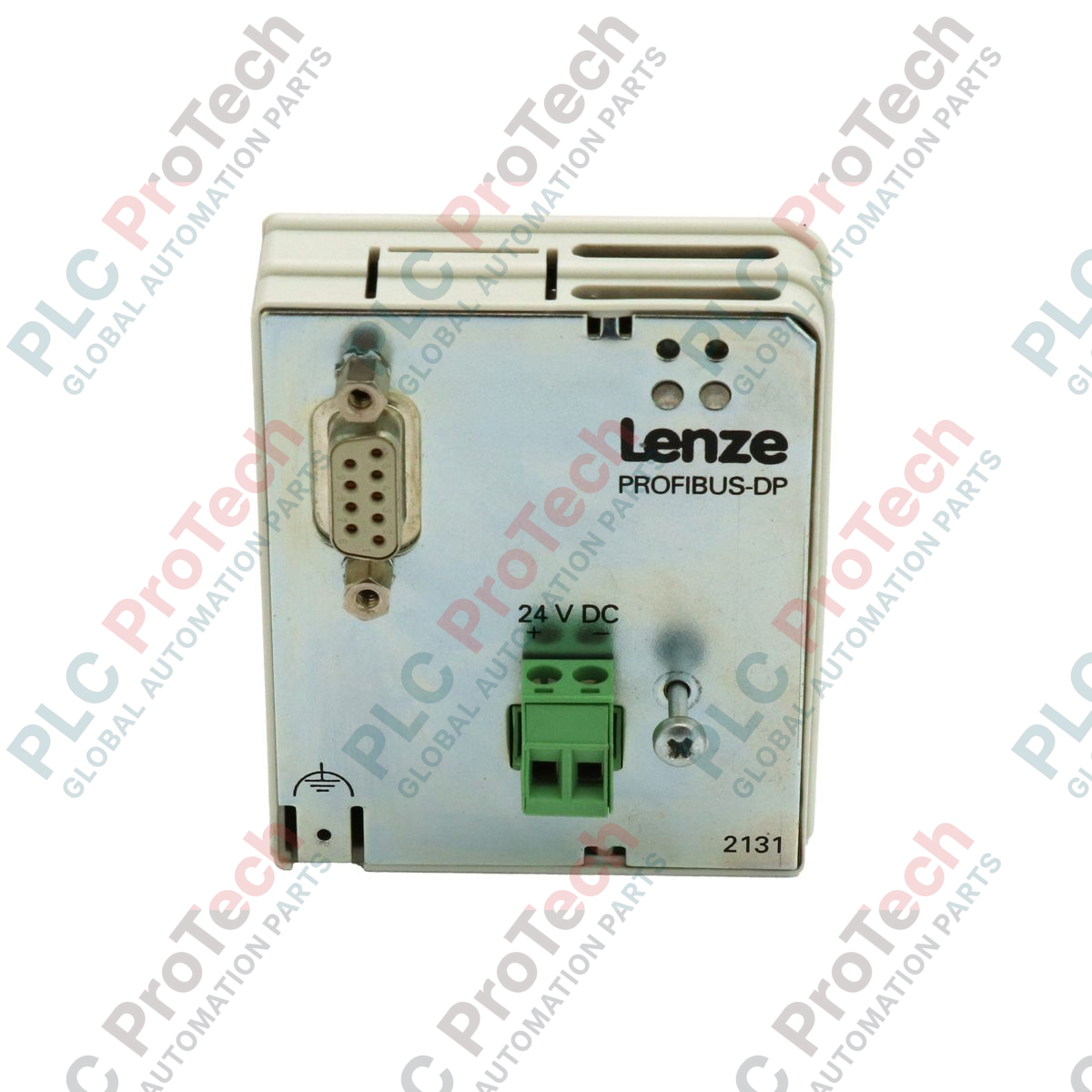
The EMF2131IB hardware is engineered to reside in the front expansion slot of the 8200-series inverter. It supports the PROFIBUS DP-V0 protocol, facilitating cyclic data exchange of process images (such as speed setpoints, actual frequency, and device status). The module features a standard 9-pin D-Sub connector for network attachment and is equipped with onboard DIP switches for station address configuration (Range 1–126). Diagnostic LEDs provide immediate visual feedback on the communication status (Run/Error), allowing for rapid on-site troubleshooting. Its low-power design draws current directly from the drive's internal bus, ensuring that no external auxiliary power supply is required for basic operation.
Technical Specifications
| Feature |
Specification |
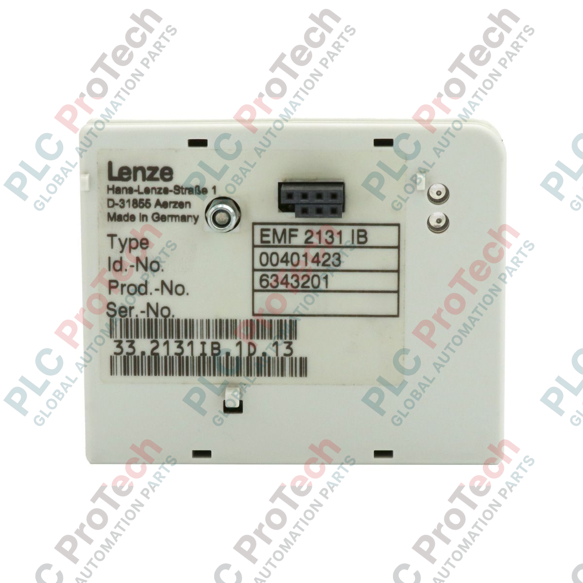
| Model |
EMF2131IB |
| Brand |
Lenze |
| Series |
8200-Series |
| Interface Type |
PROFIBUS DP |
| Communication Rate |
Up to 12 Mbit/s (Auto-detect) |
| Connector Type |
9-pin Sub-D Female |
| Address Setting |
DIP Switches (0–126) |
| Weight |
0.09 kg |
| Product Phase |
Phase-Out |
| Country of Origin |
Germany |
| Isolation |
Potential-free communication |
Technical FAQs
How do I set the PROFIBUS station address on the EMF2131IB?
The address is set via the integrated DIP switches located on the side or rear of the module. Ensure the drive is powered down before changing switch positions. The address is binary-coded; for example, to set address 3, switches 1 and 2 must be in the 'ON' position.
Does this module require a GSD file for PLC integration?
Yes. To communicate with the EMF2131IB, you must import the specific Lenze GSD file (typically LENZ2131.GSD) into your PLC hardware configuration tool (like TIA Portal or Step 7). This file defines the I/O mapping and parameter access rules for the drive.
What does a flashing red LED on the module indicate?
A flashing red LED typically indicates a "Parameterization Error" or a "Configuration Error." This means the Master PLC has established a physical connection but the data length or configuration sent by the PLC does not match the hardware settings of the EMF2131IB.
Engineering & Installation Guide
-
Network Termination: PROFIBUS requires active termination at both physical ends of the network segment. If the EMF2131IB is the last device in the chain, ensure the 9-pin Sub-D connector has the termination switch set to "ON." Failure to do so will result in intermittent telegram errors and bus instability.
-
Shielding and Grounding: Fieldbus reliability is highly dependent on proper grounding. The PROFIBUS cable shield must be grounded at the drive via the module's D-Sub shell. Ensure the drive itself has a low-impedance connection to the central PE rail to prevent ground loops from corrupting the communication data.
-
Hot-Plugging Warning: Do not insert or remove the EMF2131IB module while the frequency inverter is powered. This can cause electrical arcing across the internal system bus connectors, potentially damaging the control board of the inverter or the communication circuitry of the module.