Product Overview
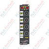
The EPP2338-1002 (EPP 2338-1002) is a versatile, high-protection industrial I/O module designed for EtherCAT P systems. This "Box" module features 8 digital channels that can be individually configured as either inputs or outputs, providing maximum flexibility for decentralized automation. Designed for direct machine mounting without a control cabinet, the EPP2338-1002 boasts an IP67 rating, making it resistant to dust, water, and harsh industrial fluids. By utilizing EtherCAT P technology, it combines ultra-fast communication and power supply (both system and peripheral voltage) into a single M8 P-coded cable, significantly reducing wiring complexity and installation costs in modular machine designs, robotics, and conveyor systems.
Technical Configuration
The EPP2338-1002 operates on the EtherCAT P standard, using 2 x M8 P-coded sockets for the bus interface to daisy-chain data and power. The I/O level features 8 x M12 (5-pin, A-coded) connectors. Each channel is highly adaptable: inputs follow the EN 61131-2 (Type 1/3) specification with a 3.0 ms filter to eliminate signal bounce, while outputs provide up to 0.5 A for ohmic, inductive, or lamp loads. The module is engineered for reliability with a 500 V electrical isolation and integrated short-circuit protection for both the sensor supply and individual output channels. Its compact, zinc die-cast or high-performance plastic housing allows for variable installation positions in temperatures ranging from -25 to +60 °C.
Technical Specifications
| Attribute |
Specification Details |
| Model |
EPP2338-1002 |
| Brand |
BECKHOFF |
| Protocol |
EtherCAT P (Communication + Power) |
| Bus Interface |
2 x M8 socket, shielded, P-coded |
| Number of Channels |
8 (Configurable as Input or Output) |
| I/O Connection |
M12 x 1, 5-pin, A-coded |
| Rated Load Voltage |
24 V DC (-15 % / +20 %) |
| Max. Output Current |
0.5 A per channel |
| Input Filter |
3.0 ms |
| Switching Times |
Typ. TON: 50 µs / TOFF: 100 µs |
| Protection Rating |
IP65, IP66, IP67 |
| Operating Temp |
-25 to +60 °C |
| Weight |
approx. 165 g |
| Shipping Weight |
2.0 kg |
Technical FAQs
What is the primary difference between EtherCAT and EtherCAT P?
While standard EtherCAT requires separate cables for data and power, EtherCAT P (used by the EPP2338-1002) integrates the EtherCAT communication and two 24 V DC power supplies ($U_S$ for system/sensors and $U_P$ for peripheral/actuators) into a single 4-wire standard Ethernet cable with specialized P-coded M8 connectors.
Can I mix inputs and outputs on the same EPP2338-1002 module?
Yes. One of the strongest features of this module is that all 8 channels are bi-directional. You do not need to pre-order specific input or output versions; you simply define the function of each pin within the TwinCAT System Manager configuration.
How does the module handle short circuits on the sensor supply?
The sensor supply is derived from the load voltage and is short-circuit proof in total, with a maximum current of 0.5 A. If a sensor cable is damaged and shorts out, the module protects the internal electronics and reports the fault back to the EtherCAT master for diagnostics.
Engineering & Installation Guide
EtherCAT P Cabling and Topology:
When installing the EPP2338-1002, ensure you use only P-coded M8 cables. Standard EtherCAT (A-coded) cables will not fit and could damage the pins if forced. Because EtherCAT P carries power, you must calculate the voltage drop across the entire string of boxes. If the $U_S$ or $U_P$ voltage drops below the 24 V DC (-15%) threshold at the end of a long chain, an EPP1322-0001 power feeder must be inserted.
M12 I/O Wiring:
The M12 sockets are 5-pin A-coded. Since the module supports 8 channels across its ports, refer to the Beckhoff pinout diagram to ensure correct wiring of sensors and actuators. Use a torque wrench to tighten the M12 connectors to 0.6 Nm to maintain the IP67 seal. Unused sockets must be fitted with protective caps to prevent moisture ingress.
Configuring in TwinCAT:
In the TwinCAT tree, the EPP2338-1002 will appear with a process image for both inputs and outputs. To use a channel as an output, simply link a PLC variable to the "Output" bit of that specific channel. The module features "Auto-Configuration" capabilities, but always verify that the "0" and "1" signal voltages match your field devices (standard 24 V logic levels).