Product Overview
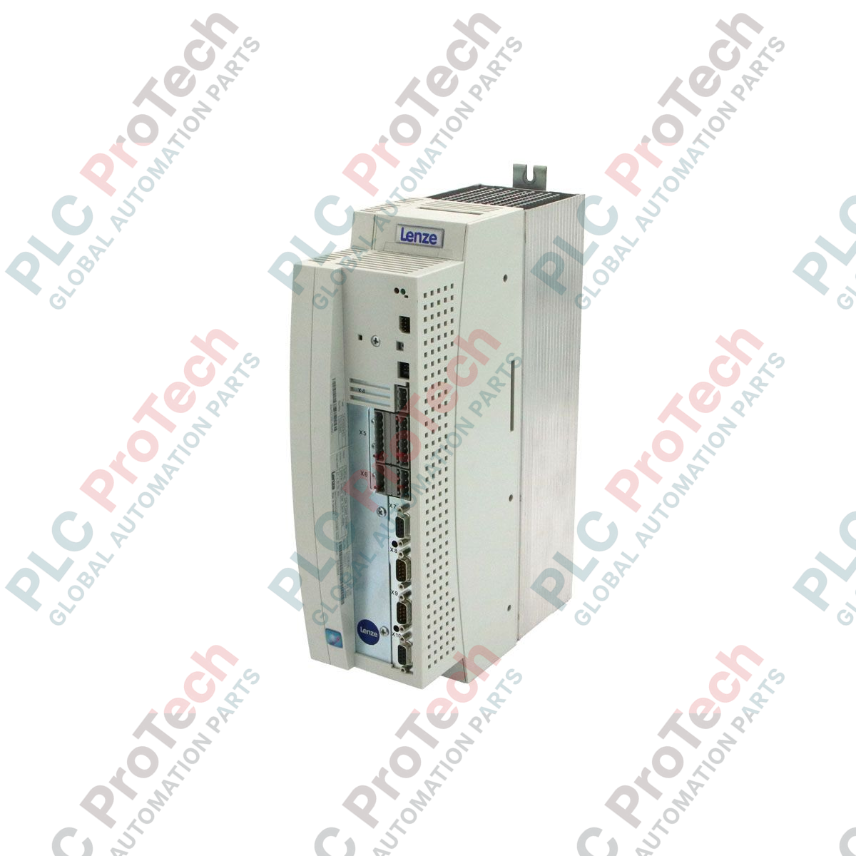
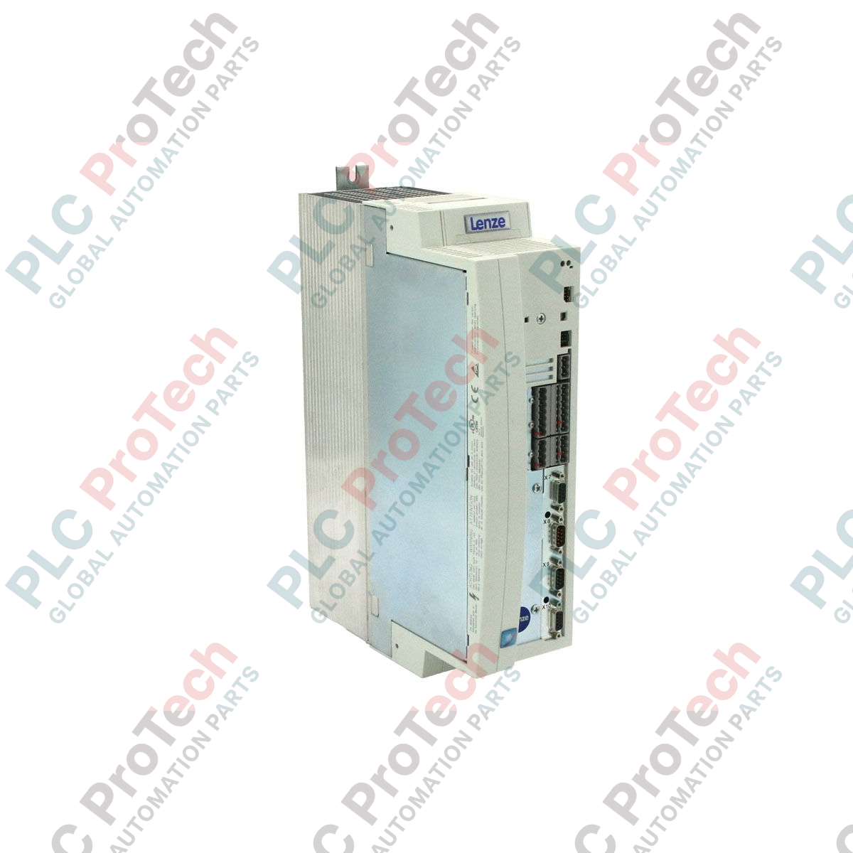
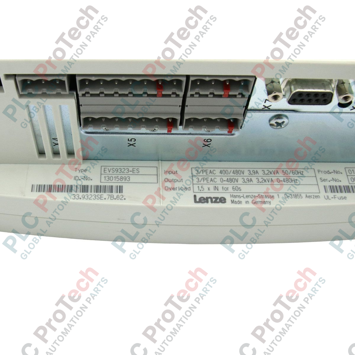
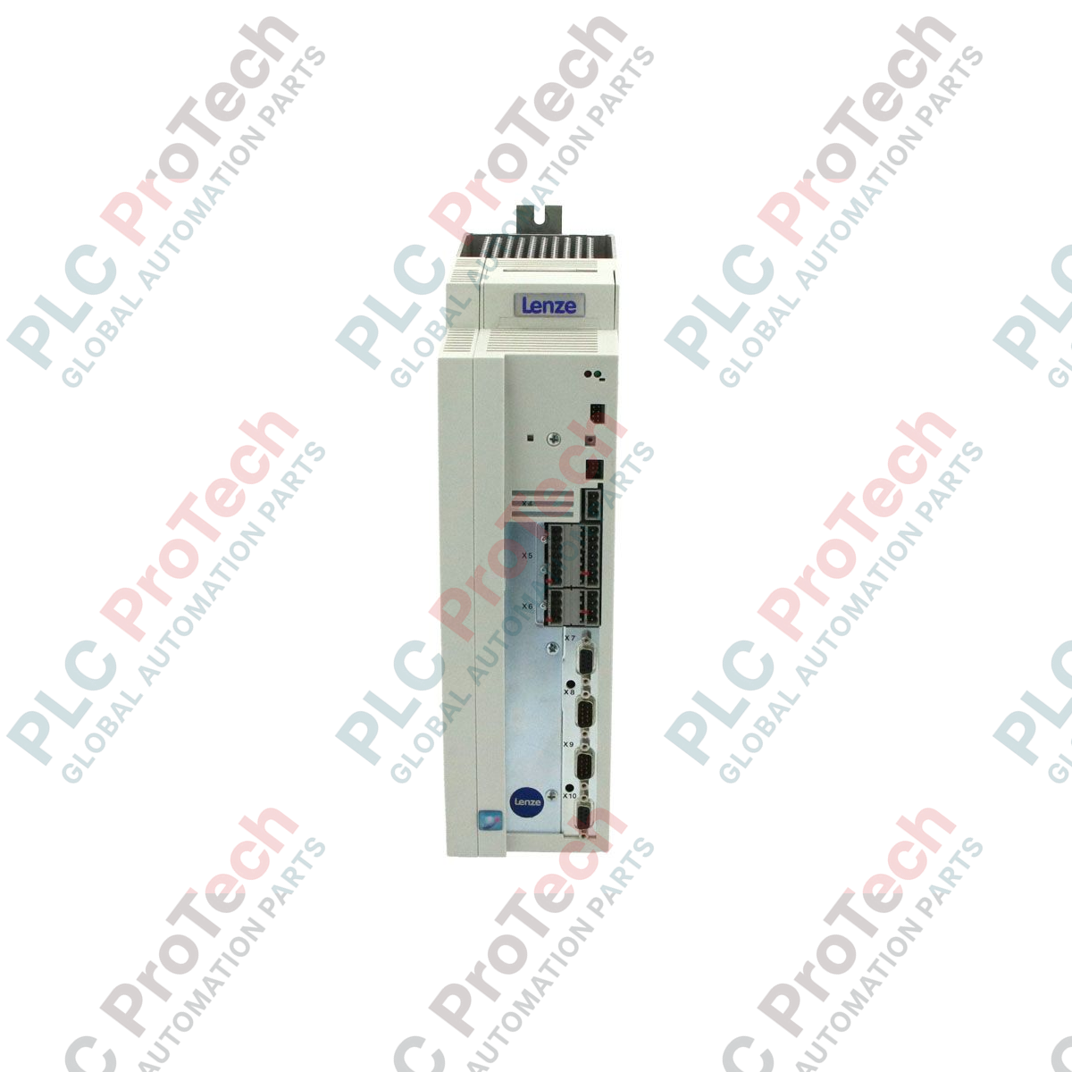
The EVS9323-ES (EVS9323-ES) is a high-precision servo inverter from the established Lenze 9300-Series, specifically engineered to provide dynamic motion control for asynchronous and synchronous servo motors. With a rated power output of 1.5 kW, this drive is a critical component for high-speed automation tasks, such as electronic camming in packaging machinery, precise tension control in textile winding, and synchronized axes in assembly robotics. The "ES" designation signifies a versatile feature set optimized for speed and torque control modes, ensuring fluid motion even under varying load conditions. Although currently in its "Phase-Out" lifecycle stage, the EVS9323-ES remains a vital solution for maintaining existing production infrastructures, offering a robust IP20-rated hardware design that guarantees long-term operational reliability and minimizes the risk of costly unscheduled downtime.
Technical Configuration
The EVS9323-ES architecture is built around a high-speed digital signal processor capable of handling complex control algorithms with minimal latency. It supports a wide range of feedback systems, including high-resolution resolvers and incremental encoders, to ensure precise closed-loop positioning. The unit is designed for a 3-phase mains connection and incorporates an integrated thermal management system within its slim 9.70 cm profile, allowing for high-density cabinet mounting. Its internal logic facilitates seamless integration with fieldbus systems through modular expansion slots, supporting protocols such as PROFIBUS and CANopen. Furthermore, the 9300-series platform includes comprehensive protection circuits for the power stage, including monitoring for motor short circuits, earth faults, and I2t motor thermal protection.
Technical Specifications
| Attribute |
Specification |
| Model |
EVS9323-ES |
| Brand |
Lenze |
| Series |
9300-Series |
| Product Type |
Servo Inverter / Drive |
| Rated Power |
1.5 kW |
| Protection Degree |
IP20 |
| Dimensions |
35.00 x 25.00 x 9.70 cm |
| Weight |
5.00 kg |
| Product Status |
Phase-Out |
| Operating Temp |
0 to 45 deg C (up to 55 deg C with derating) |
| Commodity Code |
85044095 |
| Export Control |
ECCN N |
Technical FAQs
How do I differentiate the "ES" variant from the "EP" positioning variant?
The EVS9323-ES is primarily optimized for speed and torque control loops where a master PLC handles the positioning logic. The "EP" variant contains specialized firmware for autonomous internal positioning. However, the ES version can still perform highly accurate synchronized motion when used with a motion controller over a system bus.
What software is required to parameterize the EVS9323-ES?
Commissioning is typically performed using the Lenze Global Drive Control (GDC) software. Alternatively, basic parameter adjustments and fault diagnostics can be conducted directly on the drive using the plug-in keypad module (EVS9301-K).
Is the EVS9323-ES compatible with non-Lenze motors?
Yes. While optimized for Lenze servo motors, the 9300-series firmware allows for the manual entry of motor parameters (inductance, resistance, etc.), enabling the drive to control a wide variety of third-party synchronous and asynchronous motors.
Engineering & Installation Guide
-
Thermal Management and Clearances: To ensure optimal lifespan of the internal capacitors, mount the EVS9323-ES vertically. Maintain a minimum clearance of 100 mm above and below the drive. Side-by-side mounting is supported, but if the cabinet ambient temperature exceeds 40 Celsius, a 10 mm lateral air gap is recommended to prevent thermal derating of the 1.5 kW output.
-
Shielding and Grounding: For high-precision servo applications, the motor cable shield must be clamped to the mounting plate using a large-surface contact clip directly at the drive’s PE connection point. Avoid using long grounding "pigtails," which can introduce high-frequency noise into the feedback signals, leading to encoder jitter or intermittent "Fault" trips.
-
DC Bus Safety Notice: After disconnecting the mains power, the DC bus capacitors remain charged at lethal voltage levels. Wait at least 5 minutes for the internal discharge resistors to bleed the energy before performing any wiring changes. Verify that the voltage between terminals +UG and -UG is below 50 VDC using a multimeter.