Product Overview
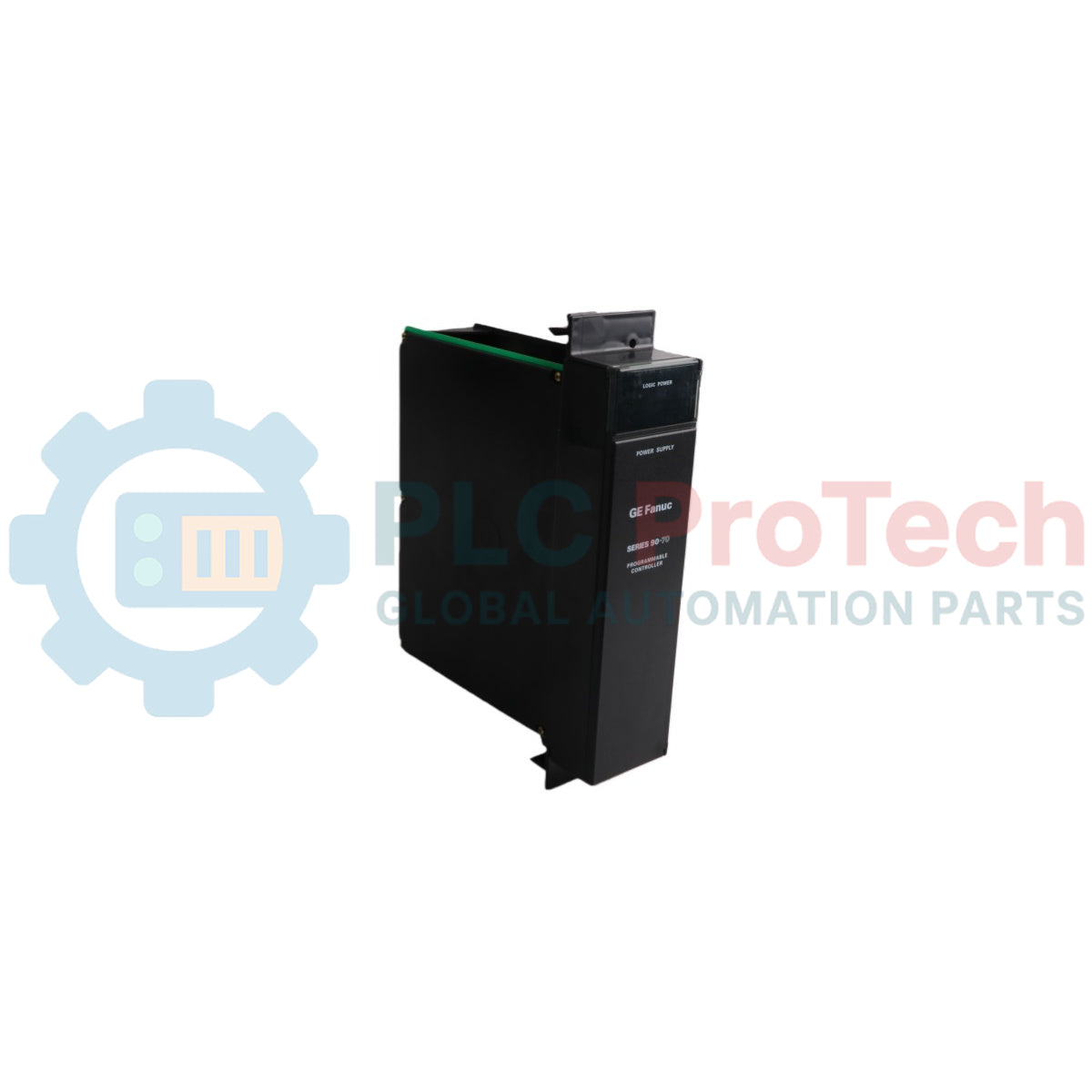
The IC697PWR711M (IC697PWR711-M) is a high-performance, 100-Watt capacity power regulation module engineered by GE Fanuc for the advanced Series 90-70 programmable logic controller infrastructure. Functioning as the primary electrical baseplate engine, this module converts wide-range AC or DC input potentials into regulated triple-rail output voltages to drive complex processing substrates. Mission-critical industrial environments—including deep-pit mining extraction rigs, municipal thermal power generation facilities, and continuous chemical distillation operations—rely on the IC697PWR711M (IC697PWR711-M) to maintain high-integrity bus processing logic. By integrating onboard active power factor correction and comprehensive electronic overcurrent clamps, the device cushions sensitive central processing frames against raw grid fluctuations. This prevents unprogrammed logic resets, isolates downstream field inductive transients, and successfully reduces expensive facility unscheduled downtime.
Mechanical Design & Power Distribution Matrix
The underlying hardware topology, multi-rail distribution framework, and fault isolation loops of the IC697PWR711M power assembly govern its real-time operational safety margins.
-
Triple-Potential DC Power Sourcing: Delivers simultaneous, high-stability rails optimized for rack logic and instrumentation interfaces, feeding +5 VDC at up to 20 A for central microprocessors, +12 VDC at 2 A for local communication loops, and -12 VDC at 1 A for operational amplifier inputs.
-
Universal Input Voltage Stage: Houses an active rectifier front-end that accepts flexible nominal incoming power profiles, operating smoothly on 120/240 VAC (90 to 264 VAC utility lines) or 125 VDC (100 to 150 VDC battery banks).
-
Onboard Power Factor Correction: Utilizes internal solid-state filtering circuitry to maintain a power factor greater than 0.93 under full load, minimizing line harmonic injection back into the switchgear cabinet.
-
Integrated Hardware Protective Clamps: Employs precise crowbar overvoltage circuits on the +5 VDC line (tripping between 5.7 and 6.7 V) alongside fast-acting typical overcurrent thresholds at 21 A (+5 VDC), 3.5 A (+12 VDC), and 1.6 A (-12 VDC).
-
Extended Hold-up Retention Loop: Provides a minimum 21-millisecond ride-through buffer upon immediate loss of incoming AC utility power, ensuring the host CPU has adequate time to execute safe shut-down subroutines and preserve volatile memory tables.
Performance Specifications & Engineering Index
| Engineering Metric |
Technical Specification Standard Values |
| Model Designation |
IC697PWR711M |
| Brand Manufacturer |
GE Fanuc / Emerson Automation Solutions |
| Control System Line |
Series 90-70 High-Performance PLC Platform |
| Module Classification |
100-Watt Core Baseplate Power Supply Module |
| Nominal Input Ranges |
120/240 VAC Nominal / 125 VDC Nominal |
| AC Operational Envelope |
90 to 264 VAC, Single Phase (47 to 63 Hz Frequency Window) |
| DC Operational Envelope |
100 to 150 VDC Continuous Battery Power Input |
| Power Consumption Profiles |
135 Watts typical / 160 Watts Maximum Input Draw |
| Input Inrush Threshold |
3 A Typical Half-Cycle Peak Current |
| Cumulative Output Power |
100 Watts Maximum total shared across all 3 rails |
| Voltage Regulation Precision |
+5 VDC: 4.90 to 5.25 V / +12 VDC: 11.75 to 12.6 V / -12 VDC: -12.6 to -11.75 V |
| Diagnostic Status Cluster |
Dedicated LED indicators for active DC outputs and overload warnings |
| Operating Ambient Window |
0 to 60 deg C Baseplate Ambient Operating Range |
| Storage Thermal Boundary |
-40 to +85 deg C Structural Storage Envelope |
| Atmospheric Humidity Limits |
5 to 95 percent Non-Condensing Environmental Ranges |
System Operations & Maintenance FAQs
How do engineers manage a vacancy left by a secondary rack power module in an expanded system?
When setting up multi-rack Series 90-70 architectures, engineers deploy the optional IC697CBL700 power supply extension cable kit. This package provides a heavy-duty interconnect cable along with a dedicated faceplate assembly designed to blank off and secure the vacant power supply slot within the expansion baseplate, ensuring proper panel aesthetics and grounding.
What behavioral changes indicate that the IC697PWR711M has entered an overcurrent condition?
The module features a front-mounted LED status array that constantly monitors load conditions. If a downstream module or communication bus draws current exceeding the 21 A clamp on the +5 VDC rail or the 3.5 A threshold on the +12 VDC line, the output rails shut down electronically to protect internal traces, and the front diagnostic LEDs toggle state to alert maintenance personnel of the field fault.
Can this power supply operate reliably when incoming line voltages drop below nominal levels for extended periods?
Yes, but you must consult the factory derating profiles (such as those outlined in standard engineering document GFK-0867B). Running continuously at the absolute lower input bound of 90 VAC decreases the thermal dissipation efficiency of the internal switching elements. To maintain long-term reliability without premature capacitor aging, engineers must derate the total active output power below the 100-Watt threshold.
Engineering & Installation Guide
-
Chassis Grounding Paths and Backplane Locking:
Mount the IC697PWR711M strictly into the leftmost slot of the Series 90-70 rack chassis. Ensure the upper and lower structural alignment teeth slide fully into the backplane frame slots, and press until the module seats firmly. Tighten all exterior frame securement screws to 0.7 N-m (6.2 inch-lbs). This establishing a low-impedance connection to the common panel earth ground, which is vital for bleeding off high-frequency electromagnetic interference before it impacts signal stability.
-
Input Power Terminal Separation and Safety Shrouding:
When landing field supply conductors onto the input terminals, use separate, high-temperature wires for AC lines or DC battery feeds. Route these supply loops away from low-voltage I/O lines to avoid capacitive noise coupling. Ensure all terminal connection blocks are protected behind their integrated plastic swing-doors to guard against accidental contact by personnel during routing diagnostics.
-
Thermal Management Clearances and Airflow Routing:
The 100-Watt power supply generates steady convective heat during continuous operations at full load. Maintain a minimal open clearance gap of 7.5 cm above and below the baseplate chassis assembly inside the cabinet. Periodically clean dust or particulates away from the lower louvers to ensure unrestricted upward airflow, keeping the ambient air around the components safely within the certified 0 to 60 deg C operating window.