1 of 3

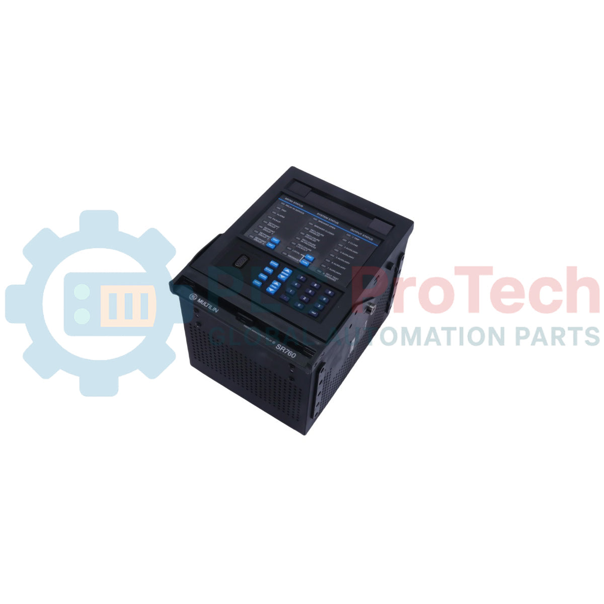
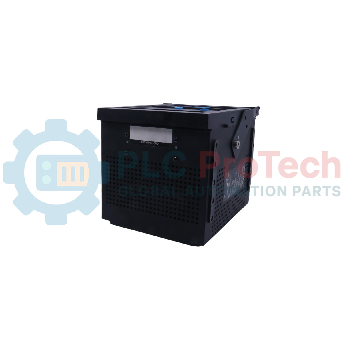
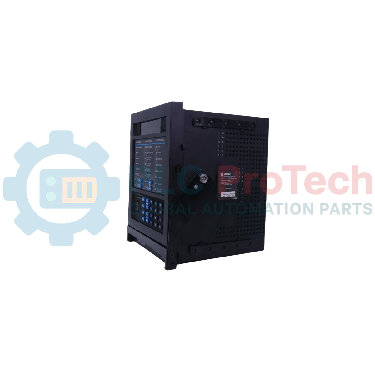
GE Multilin 760-P1-G1-S1-HI-A20-R Multilin Feeder Management Relay

GE Multilin 760-P1-G1-S1-HI-A20-R Multilin Feeder Management Relay

Only 8 item(s) left in stock
  • Manufacturer: General Electric

  • Product No.: 760-P1-G1-S1-HI-A20-R

  • Country of origin:United States

  • Product Type: Feeder Protection Relays

  • Barcode: 8537101190

  • Payment: T/T, Western Union

  • Weight: 8500g

  • Dimensions: 220 mm x 190 mm x 240 mm (H x W x D)

  • Shipping port: Xiamen

  • Warranty: 12 months

Quantity
View full details

GE Multilin 760-P1-G1-S1-HI-A20-R is a digital protection relay engineered for the comprehensive management, primary protection, and control of distribution feeders. This feeder protection system incorporates advanced overcurrent protection, voltage monitoring, and metering capabilities within a draw-out construction. It features full integration with the EnerVista software suite to facilitate streamlined configuration and event analysis.

Description

The GE Multilin 760-P1-G1-S1-HI-A20-R serves as a digital relay intended for the management and primary protection and control of distribution feeders. The device provides comprehensive protection functions for feeders and back-up protection for buses, transformers, and transmission lines. Equipped with accurate built-in metering functions, it measures current, voltage, sequence components, power, energy, and voltage. The relay possesses robust communication interfaces, utilizing multiple protocols such as ModBus RTU, DNP 3.0 Level 2, and ModBus RTU TCP/IP over an optional 10Mbps Ethernet port. It is suitable for applications in solidly grounded, high-impedance grounded, or resonant (Peterson Coil) grounded distribution systems. The architecture allows complete asset monitoring, system simulation, and advanced fault localization to enhance grid stability and equipment management.

Features

  • Complete protection functions for feeders and back-up protection for bus, transformers, and transmission lines.
  • Draw-out construction minimizes replacement time and maintenance efforts.
  • Accurate built-in metering functions eliminating the need for auxiliary metering devices.
  • Comprehensive equipment management including a trip counter, trip coil monitoring, and breaker contact wear calculations.
  • Flash memory for convenient product field upgrades.
  • IRIG-B time synchronization input for accurate event stamping.
  • Advanced oscillography and data logger supporting up to 256 power frequency cycles of waveform data.
  • Powerful built-in simulation features for verifying relay functionality against pre-fault, fault, and post-fault conditions.

Applications

  • Primary protection and control for distribution feeders on solidly grounded, high impedance grounded, or resonant (Peterson Coil) grounded systems.
  • Bus blocking and interlocking schemes.
  • High-speed fault detection for arc flash mitigation.
  • Throw over schemes (bus transfer scheme applications on loss-of-source).
  • Load shedding schemes based on voltage and frequency elements.
  • Back-up protection for transmission lines, feeders, and transformers.
  • Distributed Generation (DG) interconnect protection.

Ordering Information

Ordering Code Element Selection Description
Base Model 760 Feeder Protection System with 4 Shot Recloser
Phase Current Inputs P1 1 A phase current inputs
Ground Current Inputs G1 1 A zero sequence current inputs
Sensitive Ground Current Inputs S1 1 A sensitive ground current input
Power Supply Options HI 88-300 VDC, 70-265 VAC @48-62 Hz
Analog Outputs A20 Eight 4-20 mA analog outputs
Breaker Status LED R Red breaker closed LED

Technical Specifications

Parameter Specification
Manufacturer GE Vernova / Multilin
Phase Current Input Burden Less than 0.2 VA at 1 or 5 A
Phase Current Conversion Range 0.01 to 20 x CT (fundamental frequency only)
Ground Current Input Burden Less than 0.2 VA at 1 or 5 A
Sensitive Ground Current Input Conversion Range 0.005 to 1.000 x CT (fundamental frequency only)
Bus and Line Voltage Input Relay Input 50 V to 240 V phase-neutral
Bus and Line Voltage Input Max Continuous 273 V phase-neutral (full scale)
Logic Inputs (Dry Contacts) 1000 maximum ON resistance (32 VDC @ 2 mA provided by relay)
Logic Inputs (Wet Contacts) 30 to 300 VDC @ 2.0 mA (external DC voltage only)
Analog Input Ranges 0-1 mA, 0-5 mA, 0-10 mA, 0-20 mA, or 4-20 mA
Analog Input Impedance 375 ohm +/-10%
Solid State Trip Make and Carry 15 A @ 250 VDC for 500 ms
Output Relay Configuration 1 TRIP: Form A; 2 CLOSE: Form A; 3-7 AUXILIARY: Form C; 8 SELF-TEST WARNING: Form C
Output Relay Contact Material Silver alloy
HI Range Control Power DC = 88 to 300 V; AC = 70 to 265 V @48-62Hz
Power Consumption 25 VA nominal, 35 VA maximum
Voltage Loss Hold-up Time 30 ms
Operating Temperature Range -40 degC to +60 degC
Ambient Storage Temperature -40 degC to +85 degC
Ambient Shipping Temperature -40 degC to +85 degC
Humidity Operating up to 95% (non condensing) @ 550
Pollution Degree 2
IP Rating IP40 (front), IP20 (back)

Connections/Interfaces

Connector Pin Function
G7 / H7 Phase A Current Input
G8 / H8 Phase B Current Input
G9 / H9 Phase C Current Input
G3 / H3 Ground Current Input
G10 / H10 Neutral Current Input
G5 / H5 / G6 / H6 Phase Voltage Inputs (VA, VB, VC, VCOM)
G4 / H4 Sync Voltage Input
H11 / H12 Control Power Input
G11 / G12 Filter Ground / Chassis Ground
E1 / F1 Solid State Trip Output
E2 / F2 Output Relay 1 (TRIP)
E3 / F3 Output Relay 2 (CLOSE)
E12 / F12 Self-Test Warning Output
Front Panel Port RS232 Local Programming Port
Rear Ports RS485/RS422 Ports (COM 1 / COM 2)

Installation Guidelines

  • Grounding: Ensure reliable connection of the chassis ground to the substation safety ground grid via terminals G11/G12.
  • Shielding: Instrument and communication cable shields must be grounded at the PLC/computer end only to avoid ground loops.
  • Mounting: The device utilizes a draw-out construction designed for panel cutout installation.
  • Wiring: Current transformer (CT) secondary inputs must be routed through automatic shorting terminals to ensure safety during maintenance.
  • Passcode Protection: Configure the optional software passcode to prevent unauthorized setpoint changes from the front panel or communication ports.

Compliance and Certifications

  • cULus: UL508, UL1058, C22.2 No 14
  • CE: EN60255-5, EN50263
  • Type Tests Compliance: EN60255-5, IEC 61000-4-18, IEC 60255-22-1, EN61000-4-2, IEC 60255-22-2, EN61000-4-3, IEC 60255-22-3, EN61000-4-4, IEC 60255-22-4, EN61000-4-5, IEC 60255-22-5, EN61000-4-6, IEC 60255-22-6, CISPR11, CISPR22, IEC 60255-25, IEC 60255-21-1, IEC 60255-21-2, IEC 60255-21-3, IEC 61000-4-8, IEC 61000-4-9, IEC 61000-4-11, IEC 60529, IEC 60068-2-1, IEC 60068-2-2, IEC 60068-2-30, IEEE/ANSI C37.90.1, IEEE/ANSI C37.90.2, IEEE/ANSI C37.90.3, UL508, UL C22.2-14, UL1053

Loading product navigation…

Product Documentation

Technical Datasheet (PDF) Complete specifications and technical drawings.

Technical Datasheet

GE Multilin 760-P1-G1-S1-HI-A20-R Multilin Feeder Management Relay

What is the operating temperature range for the device?

The operating temperature range is from -40 degC to +60 degC.

Which communication protocols are supported by the relay?

The relay supports ModBus RTU, DNP 3.0 Level 2, and ModBus RTU TCP/IP protocols.

What power supply range does the HI option specify?

The HI power supply option supports a range of 88-300 VDC or 70-265 VAC at 48-62 Hz.

How many electromechanical relay outputs are available on the device?

The device features eight electromechanical relay outputs alongside one high-speed SCR solid state output.

Global Express Shipping

  • Standard Delivery: 4-6 Business Days via DHL, FedEx, and UPS.
  • Express Dispatch: Same-day dispatch for in-stock orders placed before 2:00 PM (GMT+8).
  • Worldwide Coverage: Serving over 150 countries, including rapid delivery to Saudi Arabia and UAE.

Returns & Warranty

  • 30-Day Guarantee: Returns accepted for in-stock products in original, factory-sealed packaging.
  • 12-Month Warranty: Every industrial component is backed by our professional technical warranty.

Orders are processed and delivered Monday-Friday (excluding public holidays).


For full eligibility, restocking fees, and international return details, please view our official Refund & Return Policy .

TECHNICAL SPECIFICATIONS

Color pattern
Black
Country of origin
United States

Recently Viewed Products

Technical knowledge

Why Maintenance Data Is Essential for Industrial Reliability

Maintenance data connects work orders, sensor signals, asset history, costs, and technician knowledge. Used well, it improves planning, reliability, predictive maintenance, spare-parts control, and...

Electric Actuators Designed to Replace Fluid Power Systems: A Practical Industrial Automation Guide

This article explains how integrated electric actuators, such as SMC’s e-Actuator series, are transforming industrial motion control by replacing traditional pneumatic and hydraulic systems. It...

Math Operations Using OpenPLC for Industrial Automation Applications

This article explains how PLC systems perform core mathematical operations such as addition, subtraction, multiplication, division, modulo, and exponentiation within industrial automation. It shows...

Advanced Boolean Logic with FBD PLC Programming: Practical Industrial Applications Beyond Basic Logic

The article explains several advanced Boolean logic functions used in PLC programming beyond basic AND, OR, and NOT operations. It covers how tools like truth tables, multiplexers, pulse generators,...

Boolean Logic in PLC Programming: Understanding FBD Logic Gates

Boolean logic is the foundation of every PLC program. From simple machine controls to complex industrial automation systems, logic gates determine how controllers respond to changing inputs and...

Deep-Dive Guide to Industrial Firewalls and OT Network Segmentation

Industrial firewalls play a critical role in OT cybersecurity, protecting PLC, DCS, and SCADA networks through segmentation, ingress/egress control, and IDS/IPS integration aligned with IEC 62443...