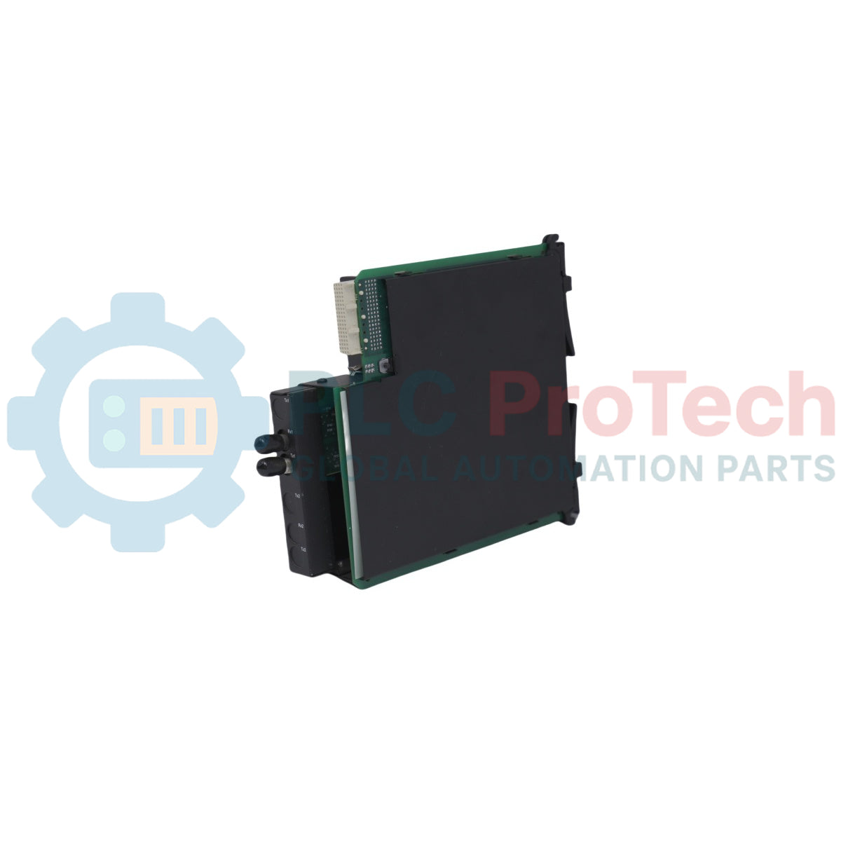
The UR-7CV is an expansion Interrelay Communications Module developed for General Electric's Universal Relay (UR) platform series. This high-density network interface block equips native protective relays with dedicated, fiber-optic long-distance signaling capabilities to link remote substations and auxiliary protection networks. Configured with the 7C hardware order designation, this module features specialized optical channels operating at a nominal infrared wavelength of 1300 nm over standard Single-Mode fiber infrastructure.
Integrating this card into an active UR chassis facilitates real-time data exchange, enabling high-speed line differential protection schemes, remote intertripping logic, and accelerated teleprotection command processing. The UR-7CV utilizes premium optical transceivers to support transmission limits across distances of up to 10 kilometers at rates up to 1 Gbps, providing consistent signal path integrity through high electromagnetic interference (EMI) environments. Engineered with standard SC/APC style connection nodes, the module supports a seamless drop-in fit behind the host enclosure's primary access faceplate.
Features
High-Bandwidth Single-Mode Interface: Optimized for 1300 nm light wave generation to allow long-distance optical communication networks.
Extended Transmission Reach: Engineered to transmit mission-critical telemetry across distances scaling up to 10 kilometers.
Deterministic Signal Paths: Supports rapid interrelay data transmission up to 1 Gbps to guarantee protection logic execution windows.
Substation Hardened Architecture: Built to isolate communication logic against severe electromagnetic interference, switching surges, and RF signals.
Plug and Play System Compatibility: Seamlessly detected by the Universal Relay core processor upon power-up, avoiding time-consuming software rebuilds.
Physical SC/APC Interface Nodes: Standardized optical couplings ensure minimized insertion loss and optical back-reflection across connections.
Applications
Multi-terminal line differential protection telecommunication links
Substation-to-substation high-speed remote direct transfer trip (DTT) schemes
High-voltage transmission line teleprotection signaling
Long-distance protective relay network segmentation over single-mode fiber backbones
Technical Specifications
Parameter
Specification
Manufacturer
GE Multilin (General Electric)
Model
UR-7CV
Product Type
Interrelay Communications Module
Product Family
Universal Relay (UR) Series
Order Code Option
7C
Wavelength
1300 nm
Fiber Media Compatibility
Single-Mode Fiber
Maximum Transmission Distance
Up to 10 kilometers
Maximum Data Rate
Up to 1 Gbps
Optical Connector Interface
SC/APC Type
Operating Temperature
-40 degC to +70 degC
Storage Temperature
-40 degC to +85 degC
Power Consumption
Typically less than 2 W
Dimensions (H x W x L)
4.5 cm x 11.0 cm x 14.0 cm
Country of Origin
United States (USA)
Installation Guidelines
Pre-Installation Power Isolation
Completely shut down the auxiliary power supply feed driving the host protective relay prior to mechanical interaction.
Do not attempt to slide or remove communications modules while the backplane bus is energized, as this can cause logic execution faults or damage to sensitive transceiver optics.
Module Insertion Mechanics
Pivot open the front assembly cover latch to expose the processing card rack.
Align the circuit card precisely inside the targeted slot guides, pushing firmly until the rear connector block mates securely with the host system backplane.
Fasten all structural faceplate mounting hardware to confirm continuous chassis grounding path integrity.
Optical Fiber Handling and Polarity
Keep the integrated dust plugs inside the SC/APC ports until the field fiber is completely terminated and ready for deployment.
Clean all optical fiber ferrules using standardized dry-wipe lint-free industrial optics cleaners before final plug-in execution.
Ensure maximum bending radius guidelines of the field fiber cables are strictly maintained within the cabinet routing layout to bypass signal attenuation faults.
FAQ
What type of optical fiber line is mandated for this module configuration?
The module is engineered exclusively to couple with standard single-mode optical fiber lines. Attempting to deploy multi-mode patch cords will create severe optical core diameter mismatching, resulting in catastrophic signal attenuation and immediate link communication failure.
How does this card communicate system line differential statuses during link anomalies?
When embedded in standard UR line protection layouts, the underlying system firmware checks packet continuity. If an optical line disruption breaks link traffic for a duration exceeding critical limits, the card logs a channel failure operand to trigger fallback master-slave backup intertripping mechanisms across alternative terminals.
Can this unit withstand high substation operating temperatures without requiring external fans?
Yes, the module is engineered to operate passively within a wide industrial scope spanning -40 degC up to +70 degC, which matches the extreme environmental conditions common inside outdoor marshalling kiosks or localized power distribution control bays.
Maintenance data connects work orders, sensor signals, asset history, costs, and technician knowledge. Used well, it improves planning, reliability, predictive maintenance, spare-parts control, and...
This article explains how integrated electric actuators, such as SMC’s e-Actuator series, are transforming industrial motion control by replacing traditional pneumatic and hydraulic systems. It...
This article explains how PLC systems perform core mathematical operations such as addition, subtraction, multiplication, division, modulo, and exponentiation within industrial automation. It shows...
The article explains several advanced Boolean logic functions used in PLC programming beyond basic AND, OR, and NOT operations. It covers how tools like truth tables, multiplexers, pulse generators,...
Boolean logic is the foundation of every PLC program. From simple machine controls to complex industrial automation systems, logic gates determine how controllers respond to changing inputs and...
Industrial firewalls play a critical role in OT cybersecurity, protecting PLC, DCS, and SCADA networks through segmentation, ingress/egress control, and IDS/IPS integration aligned with IEC 62443...
Choosing a selection results in a full page refresh.