Product Overview
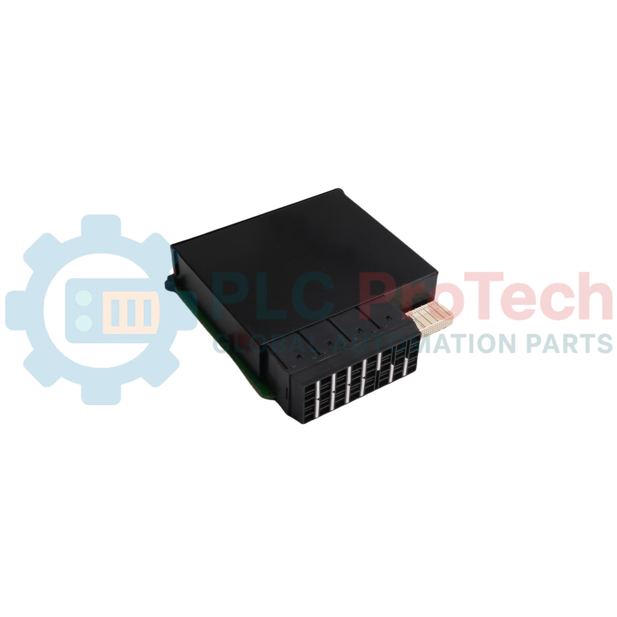
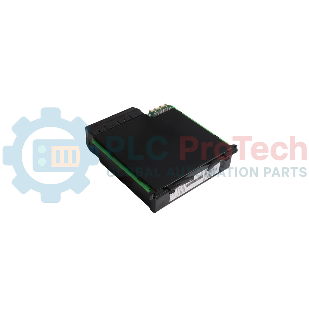
The UR-8CH is a high-integrity Current Transformer and Voltage Transformer (CT/VT) input submodule engineered by GE Multilin for the versatile UR Series Universal Relays platform. Functioning as a critical analog sensing interface, this board furnishes the host protective relay with three dedicated 1 A / 5 A phase CT channels and one highly accurate 1 A / 5 A ground CT channel. Heavy continuous-process operations—including electrical power generation utilities, petrochemical refining complexes, and high-capacity mining substations—rely on the UR-8CH to capture primary current and voltage metrics with high fidelity. By providing robust galvanic isolation from hazardous high-voltage primary circuits and transforming inputs into standardized internal secondary signals, the module protects the main CPU from transient spikes. This precise tracking allows the protection system to execute fast trip commands during phase overcurrent, ground fault, or differential upsets, significantly mitigating equipment damage and reducing unprogrammed grid downtime.
Hardware Infrastructure & Protection Mechanics
The mechanical construction, signal conditioning paths, and adaptive programming logic of the UR-8CH card support precise telemetry routing and complex electrical protection planning:
-
Dual-Range Current Inputs: Outfitted with flexible, high-accuracy phase CT inputs that accept standard 1 A or 5 A secondary inputs, adjusting smoothly to variable utility current standards.
-
Galvanic Fault Isolation: Establishes a rugged physical separation barrier between high-energy primary lines and the low-voltage microprocessor deck to shield sensitive internal components.
-
Flexible Protective Customization: Integrates seamlessly with the host relay firmware to run diverse protective layouts, such as concurrent split-phase protection, high-impedance differential tracking, and residual ground fault monitoring.
-
Advanced Signal Diagnostics: Uses dedicated hardware verification loops to continuous inspect the physical path of analog inputs, filtering out noise and confirming input signal truth before processing.
-
Dual-Layer Reliability Tracking: Combines localized hardware diagnostic routines with the broader self-health monitoring software of the UR Series chassis to flag diagnostic alarms before a sensing drop can cause a safety system failure.
Physical & Performance Benchmarks
| Hardware Parameter |
Certified Industrial Standard |
| Model Identity |
UR-8CH |
| Brand Manufacturer |
GE Multilin (General Electric) |
| Control System Line |
UR Series Universal Relays Platform |
| Module Classification |
Analog CT/VT Data Acquisition Submodule |
| Phase Current Inputs |
3 Channels (Configurable for 1 A or 5 A Secondary) |
| Ground Current Inputs |
1 Channel (Configurable for 1 A or 5 A Secondary) |
| Signal Processing Software |
EnerVista Launchpad Control Package Suite |
| Hardware Compatibility Bounds |
Fully compatible with UR Series CPUs running firmware 3.5x or older |
| Operating Thermal Envelope |
-40 to +60 deg C Ambient Temperature Window |
| Storage Temperature Bounds |
-40 to +85 deg C Maximum Structural Limits |
| Physical Weight |
1.15 kg Net Mass Base |
| Outline Dimensions |
6.0 Inches L x 7.0 Inches W x 1.5 Inches H |
| Manufacturing Origin |
Markham, Ontario, Canada |
Electrical Protection & Legacy Compatibility FAQs
How do engineers check the specific system firmware version when integrating the UR-8CH module?
Operators manage and audit the internal parameters of the protective system using the EnerVista Launchpad software package. This diagnostic station allows personnel to view the active firmware revision. Because the UR-8CH represents a legacy order code for CT/VT components, it is engineered to function inside chassis architectures operating firmware versions 3.5x or older.
What hardware restrictions occur if a system is upgraded to firmware version 4.0x or newer?
Chassis upgraded to firmware version 4.0x or more recent require a matched pairing of modern CPU modules and updated CT/VT input cards to communicate properly. Legacy submodules like the UR-8CH are not natively compatible with version 4.0x software layers, so keeping the core processor at version 3.5x or older is necessary during field maintenance swaps.
What structural advantages do the built-in current transformers offer over auxiliary protection boards?
The integrated current transformers on this module step down primary current into standard internal telemetry loops and output standardized secondary voltages. This design eliminates the need to install external auxiliary protective components, lowering wiring complexity, shrinking cabinet footprint, and reducing total system deployment costs.
Field Engineering & Installation Guide
-
Shield Grounding Methods and CT Secondary Loops:
Always route all current transformer field wiring through high-grade, twisted-pair shielded cables to prevent electromagnetic coupling from adjacent high-voltage bus ducts. Ground the cable shields at a single point on the relay cabinet enclosure wall, and keep the shield completely isolated at the field junction box. Never open-circuit the secondary circuit of a live current transformer under any circumstances, as this generates dangerous, high-voltage electrical arcs that can destroy the UR-8CH input stage and pose a severe shock hazard to operators.
-
Anti-Static ESD Protection and Chassis Alignment:
The diagnostic microchips and analog-to-digital converters mounted on the UR-8CH substrate are highly sensitive to electrostatic discharge (ESD). Field engineers must wear a properly bonded anti-static wrist strap clipped to the metal relay chassis before drawing the module from its anti-static delivery bag. Slide the card carefully into the chassis guide rails to avoid misaligning the internal backplane pins, and tighten all securing hardware to prevent vibration-induced contact resistance.
-
Environmental Controls and Terminal Block Security:
Verify that all terminal screws holding the heavy copper CT leads are tightened down to the specified factory torque settings. Loose connections can introduce serious measurement variations or dangerous localized heating under heavy current loads. Maintain the surrounding switchgear cabinet atmosphere within the certified -40 to +60 deg C operating window, checking that louvers and cooling vents are unobstructed to prevent accelerated component aging.