Product Overview
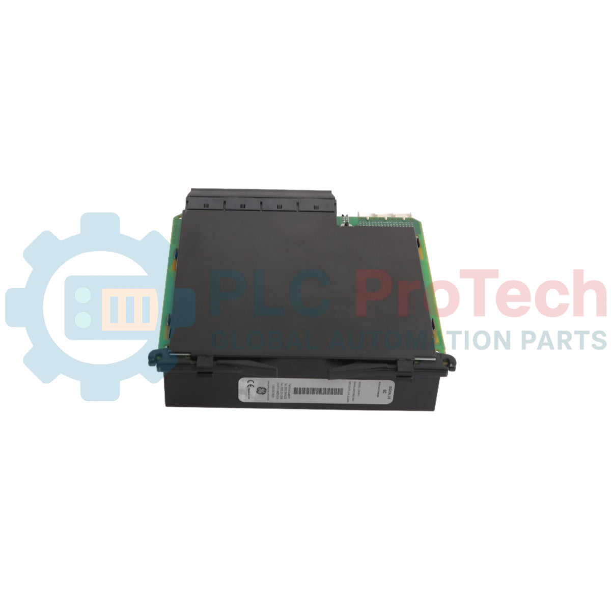
The GE UR5CH is a specialized Transducer Input/Output module designed for the Multilin Universal Relay (UR) platform. This module serves as the critical bridge between the digital protection environment and external analog equipment, allowing the relay to interface with standard industrial transducers that provide d-c milliamp (mA) or d-c voltage (V) signals.
Typically utilized in complex substation automation and industrial power monitoring, the UR5CH enables the relay to monitor non-electrical parameters (such as temperature, pressure, or vibration via external transducers) or to output control signals to analog gauges and PLC systems. By integrating these "Transducer-style" signals directly into the UR frame, the UR5CH eliminates the need for separate data acquisition hardware, centralizing all protection, control, and monitoring logic within a single, ruggedized chassis.
Technical Configuration
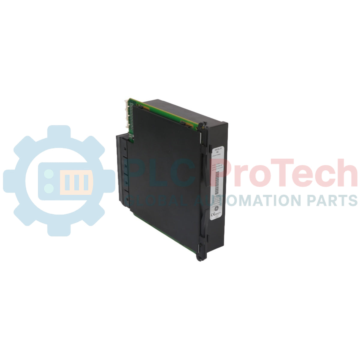
The UR5CH is a hardware-specific module designed to occupy a standard I/O slot (Slots 2 through 7) within a UR series relay (e.g., B30, C60, G60, or T60).
-
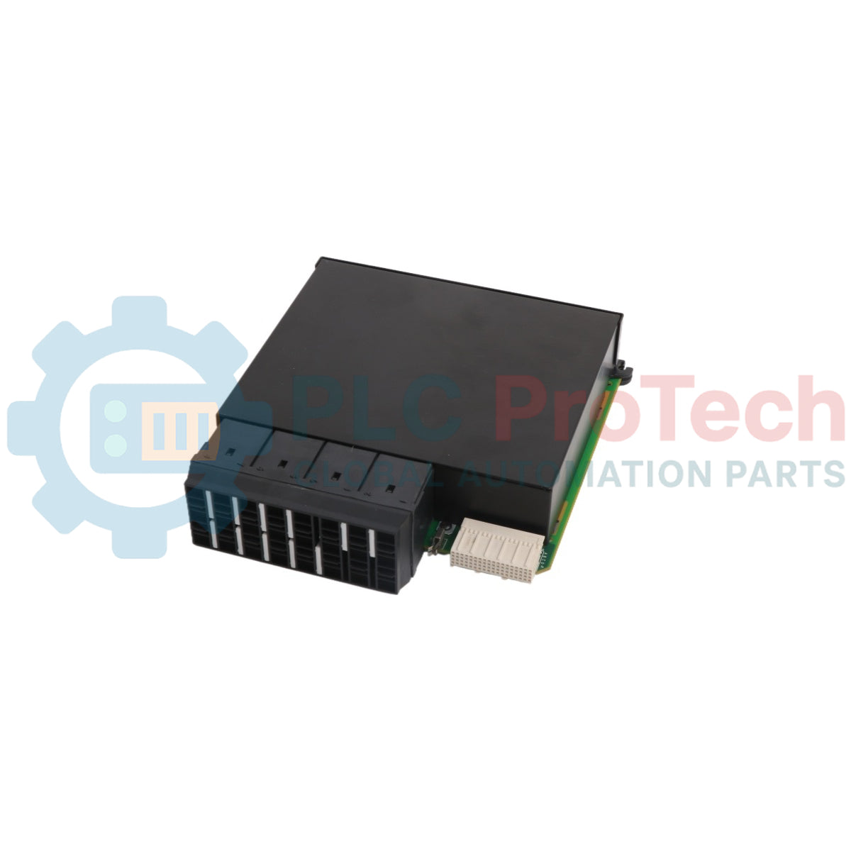
Channel Density: Features 8 independent channels that can be factory-configured or software-selected for input or output functions.
-
Signal Versatility: Supports standard industrial signal ranges, including 4-20 mA, 0-1 mA, and various d-c voltage levels (e.g., -10V to +10V).
-
High-Resolution Conversion: Employs high-precision A/D (Analog-to-Digital) and D/A (Digital-to-Analog) converters to ensure signal accuracy is maintained for sensitive control loops.
-
FlexLogic™ Integration: All transducer inputs can be used as operands within the GE FlexLogic™ engine, allowing the relay to trigger alarms or trips based on analog thresholds (e.g., "Trip if transformer oil temperature transducer exceeds 16mA").
Technical Specifications
| Parameter |
Specification Details |
| Platform |
GE Multilin Universal Relay (UR) |
| Module Type |
Transducer Input/Output (I/O) |
| Number of Channels |
8 Channels |
| Input Ranges |
±1 mA, 0-1 mA, 4-20 mA, ±10 V, 0-10 V (Option dependent) |
| Output Ranges |
4-20 mA, 0-20 mA (Option dependent) |
| Accuracy |
±0.1% of Full Scale at 25°C |
| Isolation |
2 kV Channel-to-Ground / 100 V Channel-to-Channel |
| Update Rate |
100 ms (Typical for all channels) |
Engineering Installation Guide
Reliable transducer monitoring requires meticulous attention to wiring and shielding to prevent signal "drift" or noise interference.
Wiring and Noise Mitigation
Because transducer signals are low-energy d-c levels, they are highly susceptible to electromagnetic interference. Always use twisted-pair, shielded cables for all transducer runs. The shield should be grounded only at the relay end to prevent ground loops. Avoid routing transducer cables parallel to high-voltage AC busbars or motor leads; if crossing is necessary, cross at a 90-degree angle.
Module Seating
Before installing the UR5CH, de-energize the UR relay power supply. Slide the module into its designated slot and ensure the ejector handles click into the locked position. Once powered up, use the EnerVista UR Setup software to configure the "Transducer Range" and "Scale Factor" for each channel to match the physical transducer's output.
Engineering Advantages
The UR5CH module significantly enhances the "Universal" nature of the Multilin UR platform. By supporting both inputs and outputs, it allows the relay to perform Analog Re-transmission. For example, the relay can measure a high-voltage primary current through its CT inputs and then use the UR5CH to output a proportional 4-20mA signal to a legacy SCADA RTU or a local panel meter.
Furthermore, the module includes comprehensive self-diagnostics. If a transducer wire is broken (Open Circuit) or shorted, the UR5CH detects the out-of-range signal and can trigger a "Module Not OK" alarm. This prevents the control system from making decisions based on "frozen" or erroneous data, a common failure mode in traditional analog systems.
Technical FAQs
Q1: Can I mix voltage and current inputs on the same UR5CH module?
A1: This depends on the specific ordering code of your UR5CH module. Some versions are "Current Only" or "Voltage Only," while others are hardware-configured at the factory for a specific mix. Check the module's side label for the specific channel mapping.
Q2: How do I calibrate a channel if the reading is slightly off?
A2: The UR5CH is factory-calibrated. However, you can apply a "User Offset" and "Gain" through the EnerVista software to compensate for resistance losses in long field cable runs, ensuring the value displayed on the relay HMI matches the physical measurement at the sensor.
Q3: Is the UR5CH suitable for high-speed protection trips?
A3: Transducer signals generally have an update rate of approximately 100ms. While excellent for monitoring and slow-acting control (like cooling fans or tap changers), they are not intended for high-speed "Instantaneous" electrical protection, which should be handled by the relay's CT/VT modules.
Q4: What happens to the outputs if the relay loses power?
A4: Upon loss of power, the D/A converters will de-energize, and the d-c output signals will drop to zero. Ensure your downstream control logic (in the PLC or DCS) is programmed to recognize a 0mA signal as a "Fail-Safe" or "Loss of Signal" condition.