


What Is SCADA? Supervisory Control Without Replacing the PLC
SCADA sits above PLCs and RTUs: it acquires field data, alarms operators, and issues supervisory commands across plants and remote assets—without replacing local deterministic control.

Manufacturer: Honeywell
Product No.: 51304476-175
Country of origin:United States
Product Type: DCS I/O Modules
Payment: T/T, Western Union
Weight: 500g
Dimensions: 220 mm x 170 mm x 60 mm
Shipping port: Xiamen
Warranty: 12 months
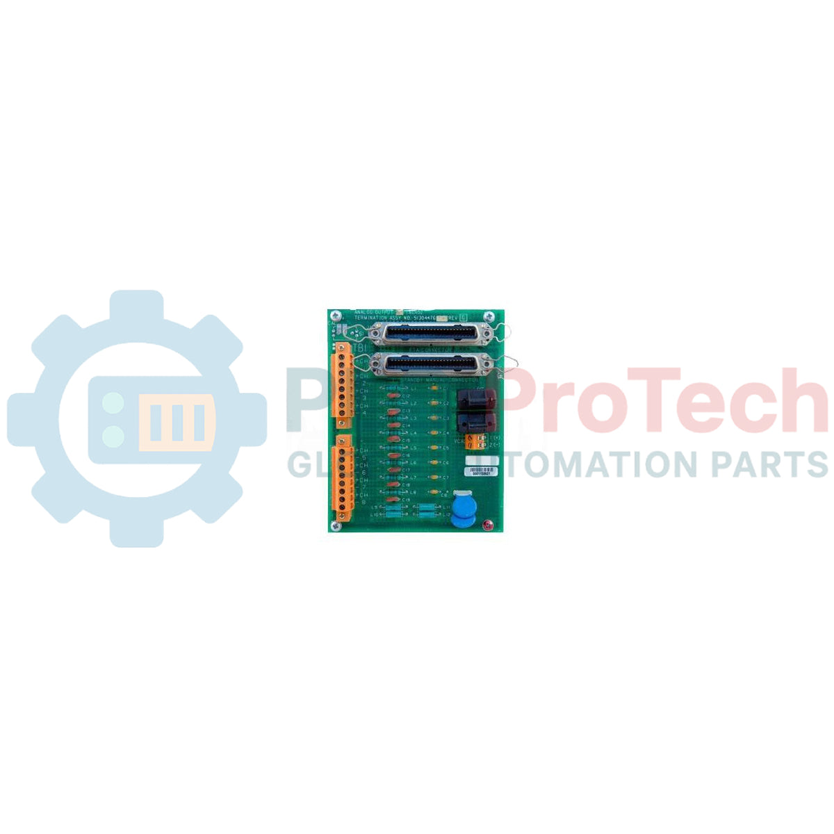
Designed to interface directly with final control elements in process environments, the Honeywell 51304476-175 serves as a highly reliable analog output interface for TDC 3000 control systems. This 8-channel, non-redundant analog output card converts digital control commands from the controller into precise, continuous 4-20mA current loops to modulate control valves, actuators, and speed drives. To ensure survivability when deployed in demanding industrial environments, the assembly features a high-grade conformal coating that resists moisture, airborne particulates, and chemical contaminants.
| Specification Parameter | Technical Value / Rating |
|---|---|
| Manufacturer | Honeywell |
| Model / Article Number | 51304476-175 |
| System Compatibility | Honeywell TDC 3000 DCS |
| Module Type | Analog Output Card (HLAO / AO) |
| Output Channels | 8 Channels |
| Redundancy Support | Non-redundant configuration |
| Wiring Connection Style | Compression Terminals |
| Environmental Protection | Conformally Coated PCB Assembly |
| Standards & Approvals | CE Compliant |
| Form Factor Size | Size A (approx. 6 inches / 152 mm) |
| Shipping Weight (Calculated) | 1.5 kg (3.3 lbs) |
| Package Dimensions (Calculated) | 220 mm x 170 mm x 60 mm |
The 51304476-175 is designed strictly for simplex (non-redundant) control architectures. If your application requires high-availability redundant loop configurations, you must specify the corresponding redundant FTA and appropriate dual-cable interface networks. Directly substituting non-redundant assemblies into redundant slots without hardware re-configuration will trigger card mismatch faults at the control node.
Pay careful attention to the loop drive limits of this module. Inadequate field loop impedance or, conversely, excessive field loop resistance exceeding 750 ohms can lead to drive current saturation or incorrect diagnostic clamp faults. Ensure that total loop resistance (including field wiring and receiver device impedance) remains within the specified operational window to prevent output channel clipping.
Always use high-quality twisted, shielded pair wiring for analog control runs. The cable shield must be grounded at one point only—typically at the DCS cabinet ground bus—to avoid creating ground loops that can induce electrical noise and skew current measurements on these sensitive 4-20mA channels.
Disconnect all electrical power sources from the carrier panel and I/O rack prior to card insertion or removal. Hand-touching the PCB contacts without proper ESD grounding straps can cause permanent electrostatic damage to the on-board solid-state components.
Global Express Shipping
Returns & Warranty
Orders are processed and delivered Monday-Friday (excluding public holidays).
For full eligibility, restocking fees, and international return details, please view our official Refund & Return Policy .
| Country of origin |
United States
|

SCADA sits above PLCs and RTUs: it acquires field data, alarms operators, and issues supervisory commands across plants and remote assets—without replacing local deterministic control.

A VFD turns fixed-frequency mains into controlled voltage and frequency so AC motors match real load—cutting pump and fan energy while tightening torque, soft-start, and braking behavior.

PLCs still run the plant floor: scan cycles, I/O, and IEC 61131-3 languages decide whether machines stay deterministic. Here is how controllers work, where they win, and where they strain.

Learning industrial automation now means mastering PLCs, networks, and protection systems—not just robots. This guide maps skills, pitfalls, and career paths for engineers entering control-heavy...

A practical guide to replacing aging Bailey Symphony operator stations running on OpenVMS Alpha. It compares Alpha emulation, OpenVMS x86 migration, OPC re-platforming, and phased ABB modernization.

Maintenance data connects work orders, sensor signals, asset history, costs, and technician knowledge. Used well, it improves planning, reliability, predictive maintenance, spare-parts control, and...