Description
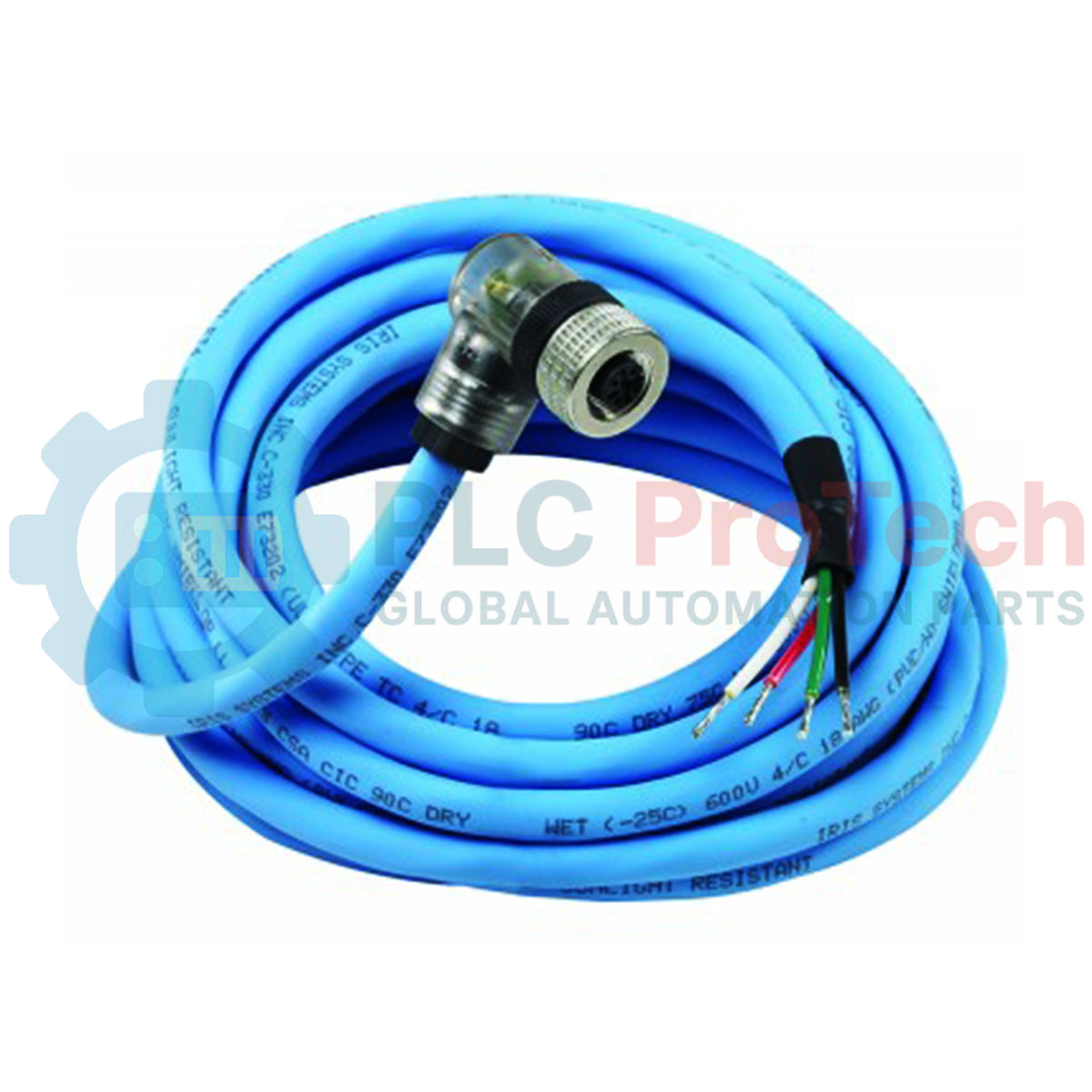
Engineered specifically to facilitate reliable signal distribution in rugged industrial environments, the Honeywell ASY782-030 functions as a heavy-duty connector cable assembly with an integrated diagnostic status indicator. This 30-foot (9-meter) cable enables direct physical and electrical connection between field sensors, actuators, or burner control system components and local control panels. The embedded LED indicator provides immediate, high-visibility visual feedback on power availability and signal status at the coupling point, minimizing troubleshooting downtime. Built with an oil-resistant, robust jacket, this assembly resists mechanical wear and chemical exposure typical of industrial manufacturing settings.
Features
-
Status Indicator: Integrated inline LED provides real-time signal and power verification at the physical junction.
-
Generous Cable Run: 30-foot (9-meter) overall length supports long-distance routing across cable trays and conduit runs.
-
Industrial Durability: Resilient outer jacket provides excellent protection against moisture, mechanical abrasion, and common industrial oils.
-
Molded Coupling: High-integrity molded connector body prevents ingress of particulate matter and fluids at the termination point.
-
Stripped Lead Ends: Free end features pre-stripped conductors for fast terminal block termination inside control panels.
Applications
- Burner control systems and flame safeguard monitoring integration.
- Remote industrial sensor-to-junction-box signaling loops.
- Process control setups requiring localized visual verification of active power paths.
- Heavy-duty machinery wiring in automotive, petrochemical, and packaging plants.
Technical Specifications
| Specification Parameter |
Value / Rating |
| Manufacturer |
Honeywell |
| Model Number |
ASY782-030 |
| Cable Length |
30 Feet (9 Meters) |
| Diagnostic Indicator |
Integrated LED Status Light |
| Connector Style |
Molded Industrial Connector to Stripped Flying Leads |
| Jacket Characteristics |
Oil-resistant, high-flexibility synthetic polymer |
| Country of Origin |
United States (or as specified by OEM) |
| Shipping Weight (Calculated) |
2.2 kg (Estimated) |
Empirical Engineering Insights
Alternative Models & Compatibility
The ASY782-030 shares pin layouts and operational design parameters with the shorter 15-foot variations (such as the ASY782-015). For systems requiring shorter physical loop distances without cable slack management, the shorter versions can be swapped directly. Ensure your electrical drawings are updated if changing run lengths, as loop resistance differs slightly over long distances.
Application Pitfalls & Engineering Notes
When deploying the 30-foot run, ensure the cable is not routed in immediate parallel proximity to high-voltage AC motor drives or heavy switching contactors to prevent electromagnetic interference from distorting low-level control signals. Although the cable outer jacket is highly durable, avoid placing sharp 90-degree bends immediately behind the molded LED connector body to prevent premature strain-relief failure under high vibration.
Commissioning & Wiring Tips
The integrated diagnostic LED relies on correct electrical polarity. If the connected device is operational but the LED does not illuminate, verify that the signal positive and return lines are not transposed. Always terminate the shield drain wire (if equipped) strictly at the panel ground bus and never at both ends, thereby preventing ground loop interference across the 9-meter distance.
Installation Guidelines
CRITICAL WARNING: De-energize all associated controllers, primary power supplies, and output relays before initiating installation or maintenance on this cable assembly. Verify that no voltage is present on the terminal block using a calibrated digital multimeter. Failure to isolate power can result in equipment damage, false triggering of safety loops, or electrical shock.
1
Inspect the molded connector end of the cable for dust, debris, or bent pins before physical engagement. Ensure the receiver socket on the device is completely clean and dry.
2
Align the physical keyway on the molded connector to the socket. Push the plug firmly home and secure the retention mechanism (coupling nut or latch) to preserve IP environmental protection ratings.
3
Route the 30-foot cable run through protective conduit or on designated trays. Maintain a minimum bend radius of ten times the overall cable diameter to prevent internal wire damage.
4
Strip the outer jacket at the control panel end to reveal the conductor insulation. Terminate according to the terminal assignments outlined in your system electrical drawings, and torque terminal block screws to the specified tension.
5
Apply system power. Trigger the field device and verify that the inline status LED lights up to confirm signal flow and power path verification.