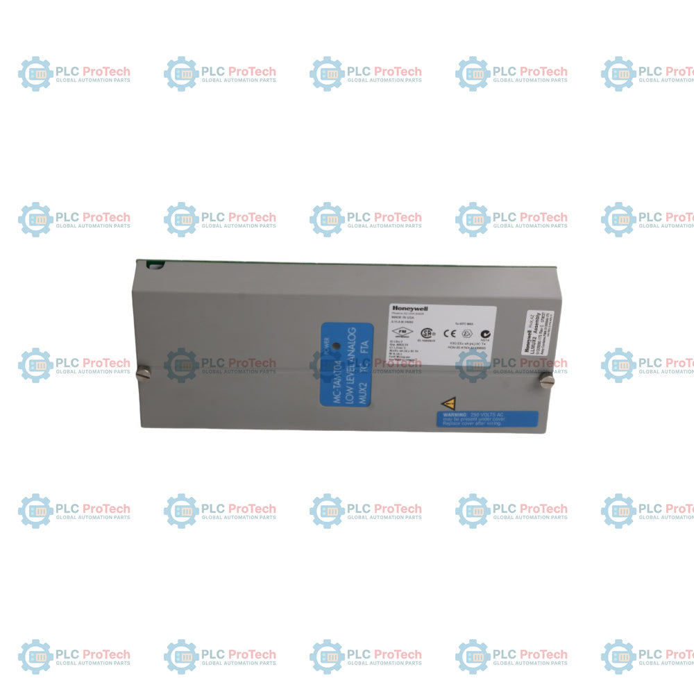
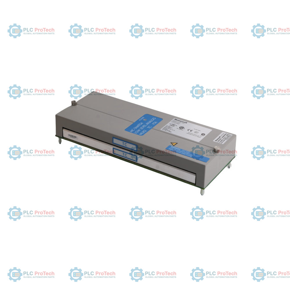
The Honeywell MC-TAMT04 (Part Number 51305890-175) is a high-reliability, 16-channel LLMUX2 Thermocouple Field Termination Assembly (FTA) engineered for integration with Honeywell Experion PKS, xPM, and Experion PMIO architectures. Utilizing advanced solid-state technology, this module replaces legacy mercury-wetted relays, eliminating environmental hazards while drastically improving loop resistance tolerances to allow longer field thermocouple wiring runs. The assembly is equipped with an integrated local Cold Junction Reference (CJR), high-performance compression terminals, a single Input/Output Processor (IOP) interface, and a robust conformal coating for continuous duty in harsh, corrosive industrial environments.
Features
-
Per-Channel Isolation: 16 fully-isolated channels providing robust channel-to-channel, channel-to-PM, and channel-to-power supply common separation.
-
Solid-State Relay Architecture: Replaces traditional mercury-wetted components to provide enhanced stability and long-term operating life.
-
Dedicated A/D Per Channel: High-performance analog-to-digital conversion circuits per channel ensure precise signal tracking.
-
Fast Open-Thermocouple Detection: Built-in advanced diagnostics identify open-circuit faults within a fixed 1-second interval.
-
Dual-Purpose Design: The same underlying 51305890-175 hardware handles both local and remote cold junction tracking through an on-board jumper configuration.
-
Corrosive Environment Protection: Factory conformally coated to meet stringent industrial atmospheric standards and maintain CE compliance.
Applications
- Experion PKS distributed control systems (DCS) process monitoring.
- High-density temperature acquisition loops in hydrocarbon processing and petrochemical facilities.
- Thermal monitoring and profiling inside gas turbines, boilers, and heavy industrial furnaces.
- Corrosive chemical processing plants requiring conformally coated process interface equipment.
Technical Specifications Table
| Parameter |
Specification |
| Manufacturer |
Honeywell |
| Model Number |
MC-TAMT04 |
| Base FTA Part Number |
51305890-175 |
| Input Channels |
16 channels (fully-isolated) |
| Input Scan Rate |
1 Second fixed by IOLP |
| Channel Bandwidth |
0 to 4.7 Hz (-3 dB) |
| Nominal Input Range |
-20 to +100 millivolts |
| Maximum Input (Non-Damaging) |
-10 to +10 volts continuous |
| Gain Error |
0.050% full scale maximum (-20 to +100 millivolt range) |
| Resolution of Reading |
2 microvolt per bit |
| Temperature Stability |
+/-20 ppm per degC maximum |
| Long Term Drift |
500 ppm |
| Input Impedance |
1 megohm at dc |
| Common Mode Voltage (CMV) |
+/-250 Vdc or Vac rms (channel-to-channel and channel-to-PM common) |
| CMRR (50 or 60 Hz) |
120 dB minimum (with 1000 ohms source impedance maximum) |
| NMRR (50 or 60 Hz) |
60 dB minimum |
| Supported Thermocouple Types |
Type J (-200 to +1200 Celsius), Type K (-100 to +1370 Celsius), Type E (-200 to +1000 Celsius), Type T (-230 to +400 Celsius), Type B (+100 to +1820 Celsius), Type S (0 to +1700 Celsius), Type R (0 to +1700 Celsius), Japan Type R' (0 to +1770 Celsius) |
| Cold Junction Compensation Range |
-20 to +60 degC |
| CJR Compensation Accuracy |
+/-0.5 degC typical |
| Surge Protection |
IEEE SWC 472-1974 certified at sensor terminals |
| Power Dissipation |
2.25 watts maximum |
| Thermal Dissipation |
7.68 Btu per hour maximum |
| Supply Voltage Range |
15 to 30 Vdc (24 Vdc nominal) |
| Supply Current |
160 milliamps at 15 Vdc |
| Operating Environmental Limits |
0 to 50 degC; 10 to 90% non-condensing relative humidity (derated to max 40 degC) |
| Storage Environmental Limits |
-40 to 80 degC |
| Agency Certifications |
CSA Certified Class 1, Division 2, Groups A, B, C, D; UL listed; CE Compliant |
| Dimensions (H x W x D) |
307.34 mm L x 124.46 mm W x 63.5 mm D (12.1 x 4.9 x 2.5 inches) |
| Country of Origin |
United States |
| Shipping Weight (Calculated) |
1.25 kg (2.75 lbs) |
| Package Dimensions (Calculated) |
360 mm x 180 mm x 100 mm |
Alternative Models & Compatibility
The MC-TAMT04 serves as a direct form, fit, and functional replacement for legacy, obsolete LLMUX TC FTA variants. It seamlessly replaces non-CE compliant boards MU-TAMT02 (51401491-100) and MC-TAMT02 (51401491-150), alongside older CE-compliant models MU-TAMT03 (51309223-125) and MC-TAMT03 (51309223-175). Notably, the base board assembly (51305890-175) is identical to the one used in the remote cold junction reference model, MC-TAMT14.
Application Pitfalls & Engineering Notes
When evaluating field thermocouple loop resistances, the solid-state architecture of the LLMUX2 provides an expanded loop driving capability compared to old mercury systems, enabling longer field cable boundaries without signaling loss. However, engineers must carefully manage enclosure thermal metrics. The assembly dissipates up to 2.25 watts continuously, yielding a heat load of 7.68 Btu per hour. Ensure proper panel venting if multiple assemblies are grouped in dense Marshalling racks to avoid crossing the maximum 40 degC operational limit under high-humidity environments.
Commissioning & Wiring Tips
The unit utilizes a 6-pin compression plug for connection at the J6 port located at the top of the board assembly. If upgrading an older non-CE legacy cabinet setup that features a 4-pin plug, the internal wires must be extracted and reworked into the 6-pin connector provided in the MC-TAMT04 shipping container. Additionally, ensure the address jumper designated as "UNIT" is set correctly to '0' or '1' to mirror the address scheme of the existing system before connecting the 50-pin J1 cable interface to the Power Adapter.
Installation Guidelines
CRITICAL WARNING: RISK OF ELECTRICAL SHOCK. Up to 250 Volts AC RMS or Vdc common mode voltage may be present underneath the primary protective plastic cover arising from external field process instrumentation loops. Disconnect all process control loop power and ensure proper lock-out/tag-out safety boundaries are fully enforced before removing the board cover or loosening field terminal connections.
1
Record the PV measurements of all active process loops from the central operations console to ensure validation benchmarks are available post-installation.
2
Unplug the primary 50-pin ribbon connector (J1) at the Power Adapter to fully decouple the LLMUX IOP from the local link system.
3
Loosen the retention screws on 8-pin terminal plug headers J1, J2, J3, and J4 to slide them away from the assembly without disconnecting field wiring leads.
4
Verify that the JMP2 jumper is set to the 'LOC' position on the replacement card to correctly engage the on-board Local Cold Junction Reference sensor circuit.
5
Mount the board into the standard enclosure tracking channel, secure the 4 corner retention standoffs, re-engage terminal headers, and reinstall the plastic safety cover.