Product Overview
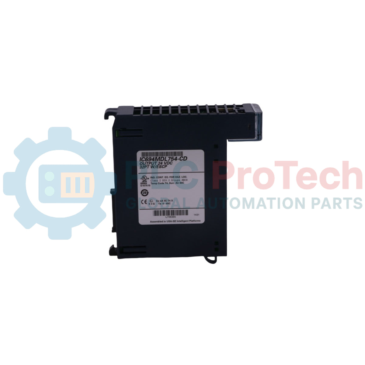
The IC694MDL754 is a high-density, smart solid-state response module engineered natively for the GE Fanuc PACSystems RX3i platform. Operating as a 12/24 VDC Positive Logic Output Module , this card channels localized power across 32 discrete output points to execute real-time actuation. Heavy automation systems—including power distribution grids, automated processing lines, and chemical blending complexes—rely on the IC694MDL754 to orchestrate downstream hardware components such as solenoid valves, external contactors, and indicating lamps. By separating the 32 discrete points into two fully isolated groups of 16 channels, the module allows facility engineers to run mixed voltage levels on a single backplane footprint. Its integrated Electronic Short-Circuit Protection (ESCP) and overtemperature diagnostics actively track circuit health, automatically trapping severe ground short faults and isolating field anomalies to prevent extended plant forced outages.
Architectural Layout & Diagnostic Attributes
The hardware framework and diagnostic operations of the IC694MDL754 logic output module maintain steady component coordination across highly dynamic field networks.
-
Dual-Group Sourcing Architecture: Divides the 32 output channels into two electrically separate blocks of 16 paths. Each group maintains an independent common line, allowing Group 1 to switch 12 VDC loads while Group 2 concurrently manages 24 VDC loads up to a maximum rating of 0.75 Amps per single channel.
-
Self-Recovering ESCP Circuitry: Features active electronic overcurrent, thermal overload, and dead short protection on every individual point. Once the underlying physical line fault or thermal overload condition is removed, the driver autonomously resets the output back to its active operational state without requiring a hard CPU reset.
-
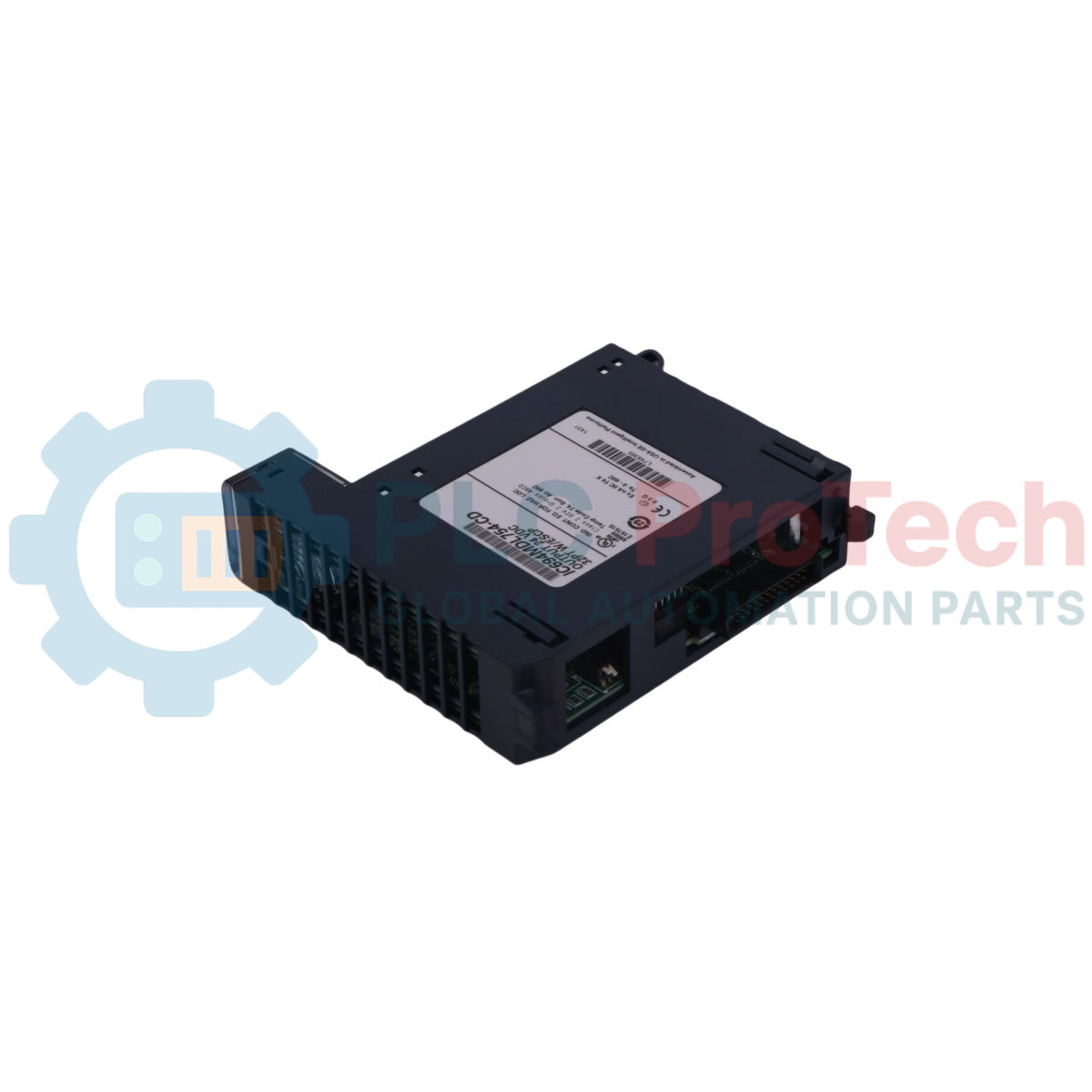
Hardware Output Default Matrix: Incorporates an on-board dual DIP switch array on the rear assembly casing used to govern system fallback operations. Technicians can configure the module to either Force Off or Hold Last State during localized communications failure.
-
Comprehensive Diagnostic Mapping: Transmits clear status codes back to the core RX3i processing unit, reporting individual point faults, external field-side power loss alarms, mechanical terminal block presence tracking, and DIP switch configuration mismatch logs.
Performance Data & Technical Specifications
| Engineering Metric |
Factory Document Specification |
| Model Designation |
IC694MDL754 |
| Brand Manufacturer |
GE Fanuc (PACSystems RX3i Series) |
| Module Classification |
Output Module, 12/24VDC, 0.75A, 32-Point Grouped, with ESCP
|
| Output Type Logic |
Sourcing Type / Positive Logic (Switches positive side of load)
|
| Output Voltage Range |
10.2 to 30 VDC
|
| Total Point Capacity |
32 Outputs (Two isolated groups of 16 channels each)
|
| Maximum Output Current |
0.75 Amps maximum per point
|
| Steady-State Overcurrent Trip |
5 Amps typical per point
|
| Maximum Inrush Current |
3 Amps supplied for 10 ms without triggering ESCP trip
|
| Channel Response Speeds |
On Response: 0.5 ms max / Off Response: 0.5 ms max
|
| Dielectric Isolation Rating |
250 VAC continuous; 1500 VAC for 1 minute (Field to Backplane & Group to Group)
|
| Backplane Power Consumption |
300 mA maximum from the internal 5 VDC logic bus
|
| Module Identification Registration |
0x059h allocation registry
|
| Compatible Terminal Blocks |
Box-style (IC694TBB032) or Spring-style (IC694TBS032)
|
Hardware Lifecycle & Troubleshooting FAQs
How do the front indicators on the IC694MDL754 distinguish between normal running conditions and live loop faults?The module integrates 32 green/yellow channel status LEDs paired with dedicated status indicators. A channel LED shines steady green when the output circuit is turned on and operating normally. If an overcurrent or short circuit occurs, the specific channel LED changes to steady yellow. Additionally, the group field power LEDs turn yellow if any point fault is detected anywhere within that isolated bank.
What occurs when an older IC694MDL754 version (-CC or earlier) experiences a complete rack power disruption while configured for Hold Last State?On firmware versions earlier than 1.20 (found on -CC and older cards), when rack power is lost and subsequently restored, the module's outputs will hold their last state but will momentarily drop to an OFF state for up to 800 ms during initialization. This interruption occurs before the CPU transitions back into RUN mode. To eliminate this momentary dropout, the module must be upgraded to firmware version 1.20 using an authorized flash utility.
Is it safe to hot-swap the IC694MDL754 module while operating within a classified hazardous area?No. While the module is certified for use in Class I, Division 2, Groups A, B, C, and D hazardous environments, a strict explosion warning applies. Technicians must completely disconnect primary system power or ensure the surrounding environment is thoroughly verified as non-hazardous before replacing, wiring, or handling modules to avoid potential static spark ignition.
Field Engineering & Installation Protocol
-
Thermal Derating and Ambient Boundaries:When operating the output card at a standard 24 VDC load profile, all 32 channels can remain continuously energized up to the maximum ambient threshold of 60 deg C without experiencing thermal issues. However, if the field supply voltage is increased to 30 VDC, a strict thermal derating curve applies above 42 deg C. At 30 VDC and a maximum ambient environment of 60 deg C, you must limit the system load configuration to a maximum of 12 concurrently active outputs to prevent automatic thermal shutdown.
-
DIP Switch Synchronization Standards:The hardware outputs default DIP switch assembly is located on the rear face of the module housing and can only be set while the module is completely removed from the backplane rack. Moving the switch to the right (open) enforces a Force Off parameter, while moving it to the left (closed) selects Hold Last State. The position of this physical hardware switch must precisely match the software attributes configured in the RX3i programming platform ; an asset mismatch will throw a configuration fault and halt the module initialization.
-
Sourcing Current Power and Common Connections:When connecting field devices to the 36-pin layout, separate power supply connections must be provided for each isolated group of 16 channels. Connect the external positive feed for channels 1–16 to Terminal 17, and its corresponding negative return line to Terminal 18. Connect the positive feed for channels 17–32 to Terminal 35, and its negative return line to Terminal 36. Do not connect these independent group feeds to a single common loop if they run on separate power sources, as this defeats the module's 250 VAC group-to-group optical safety isolation.