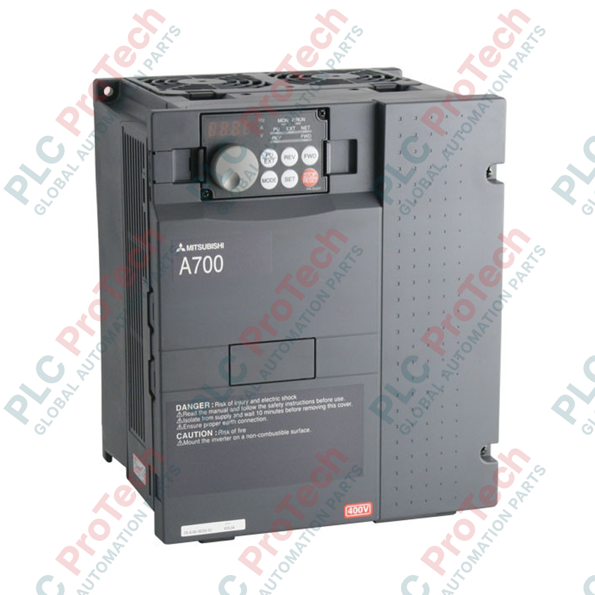
Description
Engineered to deliver high-performance motor control in demanding industrial environments, the Mitsubishi Electric FR-A740-1.5K-CHT variable frequency drive operates as a robust 3-phase speed and torque controller. Incorporating advanced vector control algorithms, this drive ensures exceptional dynamic response and steady-state speed accuracy for induction motors. The FR-A740-1.5K-CHT is built to withstand rigorous operating conditions, featuring integrated safety functions, a built-in programming terminal, and regional optimization parameters that streamline integration within standard automation systems.
Features
-
Real-Time Sensorless Vector Control: Achieves high torque at ultra-low operating speeds without requiring an encoder feedback loop.
-
Built-in PLC Functionality: Allows users to program custom control logic and sequence operations directly within the drive, reducing external controller hardware dependencies.
-
Optimized Thermal Performance: Equipped with dual internal cooling fans and premium varnished circuit boards to resist dust, humidity, and corrosive atmosphere.
-
Energy-Saving Optimization: Implements adaptive flux control to minimize motor excitation currents under partial load states, reducing energy consumption.
Applications
- Heavy-duty conveyor lines and bulk material handling systems.
- Industrial fan, blower, and centripetal pump flow regulation.
- Machine tool spindles, high-speed mixers, and extruders requiring stable torque limits.
- Automated packaging machinery and process control systems.
Technical Specifications Table
| Parameter |
Value / Specification |
| Manufacturer |
Mitsubishi Electric |
| Model Number |
FR-A740-1.5K-CHT |
| Inverter Series |
FR-A700 Series |
| Applicable Motor Capacity |
1.5 kW |
| Rated Output Current |
4.0 A |
| Rated Output Voltage |
3-phase, 380 to 480 V AC |
| Input Voltage Class |
Three-phase 400V class |
| Permissible AC Voltage Fluctuation |
325 to 528 V AC (50Hz / 60Hz) |
| Overload Capacity |
150% for 60 seconds, 200% for 3 seconds (at 50 degC) |
| Enclosure Rating |
IP20 (Open Type) |
| Cooling System |
Forced Air Cooling |
| Control Circuit Terminal Screws |
M3 x 35 mm |
| Shipping Weight (Calculated) |
5.0 kg |
| Package Dimensions (Calculated) |
270 x 190 x 180 mm |
Connections and Interfaces
| Terminal Marker |
Function Description |
| R/L1, S/L2, T/L3 |
Main 3-phase AC power input |
| U, V, W |
3-phase AC motor output connections |
| P/+, PR |
Brake resistor external connection terminals |
| STF, STR |
Forward and Reverse start signal inputs |
| SD |
Common terminal for contact input signals |
| 10, 2, 5 |
Analog input terminals for voltage speed setting |
Alternative Models & Compatibility
The "CHT" designation identifies models specifically optimized for Asian market profiles. It offers full physical and functional interchangeability with standard EU/US versions like the FR-A740-1.5K-NA. When migrating from older FR-A540 series systems, ensure parameter adaptations are executed to align with the higher resolution of the FR-A740 control loop.
Application Pitfalls & Engineering Notes
In low-speed operations under heavy loads (less than 20 Hz), standard self-cooled motors cannot dissipate heat efficiently. For continuous low-speed operations, configure thermal motor protection parameter Pr. 9 for a constant-torque motor or deploy an auxiliary blower. Keep enclosure internal temperatures below 50 Celsius to prevent premature thermal derating of the internal DC bus capacitor banks.
Commissioning & Wiring Tips
To eliminate stray capacitive leakage currents in installations with cable runs exceeding 30 meters, reduce the carrier frequency using parameter Pr. 72. Ground the inverter separately using a dedicated grounding line with a resistance of 10 ohms or less, and run signal wires separate from the main power lines by at least 10 cm to prevent electrical noise coupling.
Installation Guidelines
CRITICAL WARNING: Ensure all incoming AC lines are fully de-energized prior to terminal access. Wait a minimum of 10 minutes after disconnecting power to allow internal bus capacitors to bleed residual charge. Verify that the internal red charge lamp is completely extinguished, and test DC bus terminals P/+ to N/- with a verified voltmeter to ensure voltage is under 30 V DC before commencing work.
1
Mount the inverter vertically against a non-combustible steel panel to allow optimal convection airflow over the rear heatsinks.
2
Connect ground lines to the PE terminal before establishing main line power routing to U, V, and W output stages.
3
Torque all power terminal block connections securely to the specified OEM torque limits to mitigate high-resistance thermal junctions.