


Implementing 3-Switch XOR Ladder Logic with Internal Bit
Implement a 3-SPST switch XOR light circuit in LogixPro or RSLogix 500 using an internal relay bit. Includes truth tables, boolean equations, and verified.

Regulating three-phase asynchronous and synchronous motors in demanding industrial environments, the Mitsubishi Electric FR-A840-11K-1 is a high-performance FR-A800 series variable frequency drive engineered for high-torque applications. This inverter features an integrated FM pulse train output terminal, delivering real-world precision in speed and torque regulation across a wide 400V input range. Equipped with dynamic torque vector control and built-in PLC functionality, it coordinates complex motion sequences directly at the drive level, minimizing communication latency and system overhead.
| Specification | Value |
|---|---|
| Manufacturer | Mitsubishi Electric |
| Model Number | FR-A840-11K-1 |
| Product Series | FR-A800 Series |
| Applicable Motor Capacity | 11 kW |
| Input Voltage Class | Three-Phase 400 V Class |
| Rated Input Power Supply | Three-phase 380 to 500 V AC, 50/60 Hz |
| Output Rated Current | 23 A |
| Output Capacity | 18 kVA |
| Output Configuration | Three-Phase |
| External Communications | RS-232, RS-422, RS-485 |
| Standards | CE, UL, cUL, RoHS Compliant |
| Enclosure Protection Rating | IP20 (Open Type) |
| Dimensions (W x H x D) | 220 mm x 300 mm x 190 mm |
| Shipping Weight (Calculated) | 9.5 kg |
| Terminal / Connector | Circuit Assignment / Function Description |
|---|---|
| R/L1, S/L2, T/L3 | Main AC power input terminals (Three-phase 380-500 V) |
| U, V, W | Variable frequency three-phase output to the induction or PM motor |
| FM | Pulse train output terminal (Monitors frequency, current, or voltage) |
| SD | Common terminal for contact input and 24 V DC external power supply |
| STF / STR | Forward Rotation Start / Reverse Rotation Start control inputs |
The FR-A840-11K-1 is the direct technological successor to the legacy FR-A740-11K series in 400V industrial networks. When transitioning legacy machinery to the FR-A800 architecture, parameter lists can be converted using Mitsubishi's FR Configurator2 software. Although physical mounting dimensions are compatible, always cross-reference control terminal blocks as the FR-A800 series utilizes spring clamp terminals for control wiring compared to the screw terminals on older models.
When deploying the drive in sealed electrical panels, proper thermal management is critical. The unit generates approximately 330 Watts of heat under full-load conditions. Ensure a minimum lateral spacing of 50 mm and vertical clearance of 100 mm from adjacent equipment to avoid thermal derating. If the drive is run at high carrier frequencies (exceeding 14.5 kHz) to minimize motor acoustic noise, the rated output current must be derated by 15 percent to prevent premature thermal fault (E.THT) trips.
For motor applications requiring high starting torque at low speeds, execute an offline auto-tuning sequence (Parameter 96 set to 1) with the motor completely uncoupled. This maps the stator resistance and transient inductance, optimizing the dynamic torque vector control algorithms. Additionally, to avoid high-frequency capacitive leakage currents and EMC disruption on analog feedback loops, always use symmetrically shielded motor power cables, and ground the shielding braid 360 degrees directly at the drive grounding clamp.
CRITICAL WARNING:
Risk of electric shock and lethal discharge. Disconnect all main power inputs (R/L1, S/L2, T/L3) before opening the terminal cover or executing any maintenance. Wait at least 10 minutes for internal capacitors to discharge completely, and verify that the charge lamp is fully extinguished prior to working on internal electrical terminals.
Global Express Shipping
Returns & Warranty


Manufacturer: Mitsubishi Electric
Product No.: FR-A840-11K-1
Country of origin:United States
Product Type: Variable Frequency Drives
Payment: T/T, Western Union
Weight: 9500g
Dimensions: 220 mm x 300 mm x 190 mm
Shipping port: Xiamen
Warranty: 12 months
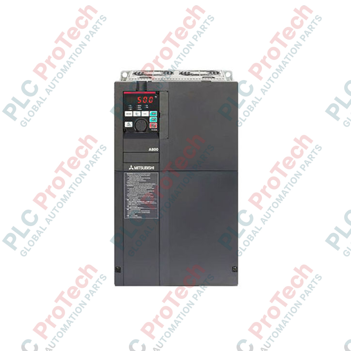
Regulating three-phase asynchronous and synchronous motors in demanding industrial environments, the Mitsubishi Electric FR-A840-11K-1 is a high-performance FR-A800 series variable frequency drive engineered for high-torque applications. This inverter features an integrated FM pulse train output terminal, delivering real-world precision in speed and torque regulation across a wide 400V input range. Equipped with dynamic torque vector control and built-in PLC functionality, it coordinates complex motion sequences directly at the drive level, minimizing communication latency and system overhead.
| Specification | Value |
|---|---|
| Manufacturer | Mitsubishi Electric |
| Model Number | FR-A840-11K-1 |
| Product Series | FR-A800 Series |
| Applicable Motor Capacity | 11 kW |
| Input Voltage Class | Three-Phase 400 V Class |
| Rated Input Power Supply | Three-phase 380 to 500 V AC, 50/60 Hz |
| Output Rated Current | 23 A |
| Output Capacity | 18 kVA |
| Output Configuration | Three-Phase |
| External Communications | RS-232, RS-422, RS-485 |
| Standards | CE, UL, cUL, RoHS Compliant |
| Enclosure Protection Rating | IP20 (Open Type) |
| Dimensions (W x H x D) | 220 mm x 300 mm x 190 mm |
| Shipping Weight (Calculated) | 9.5 kg |
| Terminal / Connector | Circuit Assignment / Function Description |
|---|---|
| R/L1, S/L2, T/L3 | Main AC power input terminals (Three-phase 380-500 V) |
| U, V, W | Variable frequency three-phase output to the induction or PM motor |
| FM | Pulse train output terminal (Monitors frequency, current, or voltage) |
| SD | Common terminal for contact input and 24 V DC external power supply |
| STF / STR | Forward Rotation Start / Reverse Rotation Start control inputs |
The FR-A840-11K-1 is the direct technological successor to the legacy FR-A740-11K series in 400V industrial networks. When transitioning legacy machinery to the FR-A800 architecture, parameter lists can be converted using Mitsubishi's FR Configurator2 software. Although physical mounting dimensions are compatible, always cross-reference control terminal blocks as the FR-A800 series utilizes spring clamp terminals for control wiring compared to the screw terminals on older models.
When deploying the drive in sealed electrical panels, proper thermal management is critical. The unit generates approximately 330 Watts of heat under full-load conditions. Ensure a minimum lateral spacing of 50 mm and vertical clearance of 100 mm from adjacent equipment to avoid thermal derating. If the drive is run at high carrier frequencies (exceeding 14.5 kHz) to minimize motor acoustic noise, the rated output current must be derated by 15 percent to prevent premature thermal fault (E.THT) trips.
For motor applications requiring high starting torque at low speeds, execute an offline auto-tuning sequence (Parameter 96 set to 1) with the motor completely uncoupled. This maps the stator resistance and transient inductance, optimizing the dynamic torque vector control algorithms. Additionally, to avoid high-frequency capacitive leakage currents and EMC disruption on analog feedback loops, always use symmetrically shielded motor power cables, and ground the shielding braid 360 degrees directly at the drive grounding clamp.
CRITICAL WARNING:
Risk of electric shock and lethal discharge. Disconnect all main power inputs (R/L1, S/L2, T/L3) before opening the terminal cover or executing any maintenance. Wait at least 10 minutes for internal capacitors to discharge completely, and verify that the charge lamp is fully extinguished prior to working on internal electrical terminals.
Global Express Shipping
Returns & Warranty
Orders are processed and delivered Monday-Friday (excluding public holidays).
For full eligibility, restocking fees, and international return details, please view our official Refund & Return Policy .
| Country of origin |
United States
|

Implement a 3-SPST switch XOR light circuit in LogixPro or RSLogix 500 using an internal relay bit. Includes truth tables, boolean equations, and verified.

Integrate Allen-Bradley CompactLogix, Caterpillar ATS, and generators into DeltaV DCS over Modbus RTU. Covers ProSoft MVI69-MCM, Miille DIN266 gateways.

ONS instruction fires but the OTE coil never latches in Studio 5000 because the one-shot is only true for one scan. Use OTL/OTU or seal-in logic instead.

Configure Allen-Bradley Kinetix 5500 servo drives on EtherNet/IP. Covers CIP Sync, IEEE 1588 V2 timing, Stratix selection, DLR topology, and HMI.

A moving-average filter is the sliding-window smoother most instrument engineers drop into DCS and PLC analog paths. Here is how the window works, how N and sample time set lag, and when a...

On Frame 5–9 gas turbines, GE Mark VI and Mark VIe run control as function-block application software. This article maps process, protection, and sequencing functions—and what Toolbox ST access...