


Implementing 3-Switch XOR Ladder Logic with Internal Bit
Implement a 3-SPST switch XOR light circuit in LogixPro or RSLogix 500 using an internal relay bit. Includes truth tables, boolean equations, and verified.

Regulating three-phase induction and permanent magnet synchronous motors in heavy industrial networks is the primary function of the Mitsubishi Electric FR-A840-18.5K-1 variable frequency drive. This high-performance inverter from the elite FR-A800 series delivers an output capacity of 18.5 kW under Normal Duty (ND) conditions, offering superior speed and torque vector control. Operating on a 400V input voltage class, it integrates a specialized FM terminal configuration for high-speed pulse train monitoring. Embedded with standard RS-485, RS-422, and RS-232 serial interfaces, this unit supports smooth automation network integration while maintaining strict compliance with CE, UL, and cUL regulatory requirements.
| Specification Parameter | Value / Rating |
|---|---|
| Manufacturer | Mitsubishi Electric |
| Model Number | FR-A840-18.5K-1 |
| Applicable Motor Capacity | 18.5 kW (Normal Duty) / 22 kW (Light Duty) |
| Output Rated Current | 38 A (Normal Duty) |
| Output Capacity | 29 kVA |
| Input Rated Voltage / Frequency | Three-phase 380 to 500 V AC, 50/60 Hz |
| Output Rated Voltage | Three-phase 380 to 500 V AC |
| Control Monitor Terminal Type | FM terminal (pulse train monitor) |
| Communication Interface | RS-232 / RS-422 / RS-485 |
| Enclosure Protection Rating | IP20 (Open Type) |
| Standards / Conformity | CE, UL, cUL, KC, RoHS |
| Height | 400 mm |
| Width | 250 mm |
| Depth | 190 mm |
| Shipping Weight (Calculated) | 16.0 kg |
This unit replaces legacy FR-A740-18.5K models. While physical mounting footprints are highly similar, wiring layouts and the digital keypads differ. Use Mitsubishi's FR Configurator2 software to import existing FR-A700 parameter profiles and convert them directly to FR-A800 compatible formats. Ensure that terminal "FM" (pulse output) configuration is matched, as the alternative "AM" (analog voltage) variant has distinct hardware wiring requirements.
The FR-A840-18.5K-1 features dual overload ratings: Normal Duty (ND) and Light Duty (LD). For heavy cyclic applications like escalators or reciprocating compressors, keep parameter settings configured to ND (150% overload capacity). Operating in LD mode (22 kW output) on heavy torque loads will trigger premature E.THT (Inverter Overload) or E.OC1 (Overcurrent during acceleration) trip states. Ensure minimum clearance guidelines (100 mm top and bottom) are strictly maintained inside electrical panels to ensure proper heat sink thermal convection.
The FM feedback loop is susceptible to electromagnetic interference (EMI). Run all pulse monitoring cables in dedicated grounded steel conduits or use shielded twisted-pair (STP) lines. Ground the shield exclusively at the drive’s protective earth terminal (PE) and avoid routing control wires parallel to high-power motor cables (U, V, W) to prevent noise induction on the pulse train signals.
CRITICAL WARNING:
Isolate and lock out all AC input power before beginning physical mounting or electrical termination. Wait at least 10 minutes post de-energization to allow internal DC bus link capacitors to fully bleed down. Measure DC voltage across terminals P/+ and N/- using a calibrated digital multimeter to verify the voltage is below 30V DC before starting work.
Global Express Shipping
Returns & Warranty


Manufacturer: Mitsubishi Electric
Product No.: FR-A840-18.5K-1
Country of origin:United States
Product Type: Variable Frequency Drives
Payment: T/T, Western Union
Weight: 16000g
Shipping port: Xiamen
Warranty: 12 months
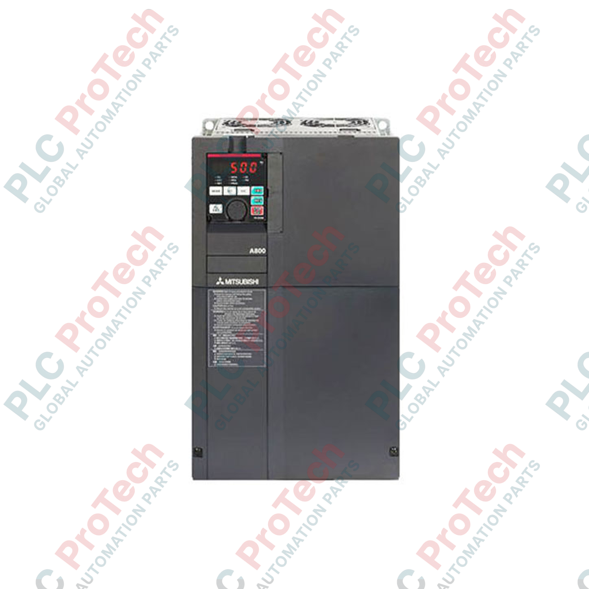
Regulating three-phase induction and permanent magnet synchronous motors in heavy industrial networks is the primary function of the Mitsubishi Electric FR-A840-18.5K-1 variable frequency drive. This high-performance inverter from the elite FR-A800 series delivers an output capacity of 18.5 kW under Normal Duty (ND) conditions, offering superior speed and torque vector control. Operating on a 400V input voltage class, it integrates a specialized FM terminal configuration for high-speed pulse train monitoring. Embedded with standard RS-485, RS-422, and RS-232 serial interfaces, this unit supports smooth automation network integration while maintaining strict compliance with CE, UL, and cUL regulatory requirements.
| Specification Parameter | Value / Rating |
|---|---|
| Manufacturer | Mitsubishi Electric |
| Model Number | FR-A840-18.5K-1 |
| Applicable Motor Capacity | 18.5 kW (Normal Duty) / 22 kW (Light Duty) |
| Output Rated Current | 38 A (Normal Duty) |
| Output Capacity | 29 kVA |
| Input Rated Voltage / Frequency | Three-phase 380 to 500 V AC, 50/60 Hz |
| Output Rated Voltage | Three-phase 380 to 500 V AC |
| Control Monitor Terminal Type | FM terminal (pulse train monitor) |
| Communication Interface | RS-232 / RS-422 / RS-485 |
| Enclosure Protection Rating | IP20 (Open Type) |
| Standards / Conformity | CE, UL, cUL, KC, RoHS |
| Height | 400 mm |
| Width | 250 mm |
| Depth | 190 mm |
| Shipping Weight (Calculated) | 16.0 kg |
This unit replaces legacy FR-A740-18.5K models. While physical mounting footprints are highly similar, wiring layouts and the digital keypads differ. Use Mitsubishi's FR Configurator2 software to import existing FR-A700 parameter profiles and convert them directly to FR-A800 compatible formats. Ensure that terminal "FM" (pulse output) configuration is matched, as the alternative "AM" (analog voltage) variant has distinct hardware wiring requirements.
The FR-A840-18.5K-1 features dual overload ratings: Normal Duty (ND) and Light Duty (LD). For heavy cyclic applications like escalators or reciprocating compressors, keep parameter settings configured to ND (150% overload capacity). Operating in LD mode (22 kW output) on heavy torque loads will trigger premature E.THT (Inverter Overload) or E.OC1 (Overcurrent during acceleration) trip states. Ensure minimum clearance guidelines (100 mm top and bottom) are strictly maintained inside electrical panels to ensure proper heat sink thermal convection.
The FM feedback loop is susceptible to electromagnetic interference (EMI). Run all pulse monitoring cables in dedicated grounded steel conduits or use shielded twisted-pair (STP) lines. Ground the shield exclusively at the drive’s protective earth terminal (PE) and avoid routing control wires parallel to high-power motor cables (U, V, W) to prevent noise induction on the pulse train signals.
CRITICAL WARNING:
Isolate and lock out all AC input power before beginning physical mounting or electrical termination. Wait at least 10 minutes post de-energization to allow internal DC bus link capacitors to fully bleed down. Measure DC voltage across terminals P/+ and N/- using a calibrated digital multimeter to verify the voltage is below 30V DC before starting work.
Global Express Shipping
Returns & Warranty
Orders are processed and delivered Monday-Friday (excluding public holidays).
For full eligibility, restocking fees, and international return details, please view our official Refund & Return Policy .
| Country of origin |
United States
|

Implement a 3-SPST switch XOR light circuit in LogixPro or RSLogix 500 using an internal relay bit. Includes truth tables, boolean equations, and verified.

Integrate Allen-Bradley CompactLogix, Caterpillar ATS, and generators into DeltaV DCS over Modbus RTU. Covers ProSoft MVI69-MCM, Miille DIN266 gateways.

ONS instruction fires but the OTE coil never latches in Studio 5000 because the one-shot is only true for one scan. Use OTL/OTU or seal-in logic instead.

Configure Allen-Bradley Kinetix 5500 servo drives on EtherNet/IP. Covers CIP Sync, IEEE 1588 V2 timing, Stratix selection, DLR topology, and HMI.

A moving-average filter is the sliding-window smoother most instrument engineers drop into DCS and PLC analog paths. Here is how the window works, how N and sample time set lag, and when a...

On Frame 5–9 gas turbines, GE Mark VI and Mark VIe run control as function-block application software. This article maps process, protection, and sequencing functions—and what Toolbox ST access...