


First TwinCAT PLC Project on a Beckhoff IPC
Build and verify a first TwinCAT PLC project on a Beckhoff IPC. This checklist covers target selection, EtherCAT discovery, I/O mapping, safe activation, restart tests, and commissioning records.
Manufacturer: Mitsubishi Electric
Product No.: FR-A840-5.5K-1
Country of origin:United States
Product Type: Variable Frequency Drives
Payment: T/T, Western Union
Weight: 8000g
Dimensions: 260 mm x 220 mm x 170 mm
Shipping port: Xiamen
Warranty: 12 months
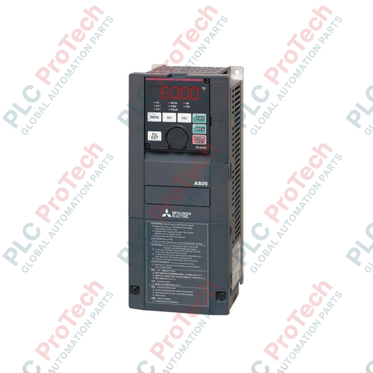
Managing heavy-duty motor operations requires precise speed regulation and high torque response. The Mitsubishi Electric FR-A840-5.5K-1 variable frequency drive delivers exceptional vector control and real-time sensorless control for three-phase induction and permanent magnet motors. This inverter is engineered for highly demanding automation layouts, providing reliable performance, structural durability, and multi-protocol network capabilities within a compact chassis.
| Manufacturer | Mitsubishi Electric |
| Model Number | FR-A840-5.5K-1 |
| Applicable Motor Capacity | 5.5 kW |
| Input Voltage Class | Three-phase 400 V AC (380 to 500 V at 50/60 Hz) |
| Output Rated Voltage | Three-phase 380 to 500 V AC |
| Output Rated Current | 12 A |
| Output Capacity | 9.1 kVA |
| Serial Communications | RS-232, RS-422, RS-485 |
| Enclosure Protection Class | IP20 |
| Standards | CE, UL, cUL |
| Dimensions (H x W x D) | 260 mm x 220 mm x 170 mm |
| Shipping Weight (Calculated) | 8.0 kg |
| Terminal / Port | Function / Circuit Assignment |
|---|---|
| R/L1, S/L2, T/L3 | Three-phase AC power input |
| U, V, W | Three-phase AC output to induction/PM motor |
| P/+, PR | External brake resistor connection |
| PU Connector | RJ-45 port for parameter unit (FR-PU07) or RS-485 connection |
| SD, PC, 5 | Control circuit common and power supply lines |
The FR-A840-5.5K-1 belongs to the flagship A800 inverter range, succeeding the legacy FR-A740 series. While physical footprints are largely compatible, wiring terminal alignments differ slightly. Parameter migration from older installations is streamlined via the FR Configurator2 software, allowing automatic conversion of legacy registers to the newer, high-resolution parameters of the current platform.
When mounting this drive within closed electrical panels, adequate ventilation is essential. Under continuous 12 A load conditions, heat dissipation can lead to thermal tripping if localized temperatures rise above 50 degC. Ensure a minimum clearance of 50 mm on both sides and 100 mm top and bottom. Avoid routing high-voltage motor output cables parallel to low-voltage sensor cables to prevent electromagnetic coupling.
When using dynamic braking configurations, ensure that the parameter settings for brake deceleration duty cycles match the thermal ratings of the external resistors. Always connect a dedicated ground wire directly from the drive's ground terminal to the main system ground bus to mitigate leakage currents and transient voltage spikes.
CRITICAL WARNING:
De-energize all primary and secondary power sources prior to installation. Internal main circuit capacitors hold highly lethal residual voltage. Wait a minimum of 10 minutes after disconnecting power, and verify that the charge LED indicator has extinguished before touching any terminals or wiring structures.
Mount the drive vertically to flat, solid surfaces in a well-ventilated enclosure.
Connect three-phase input power lines to R/L1, S/L2, and T/L3 terminals. Do not apply input power to output terminals.
Wire motor leads to U, V, and W terminals using shielded, low-impedance cabling.
Secure all cover plates, apply power, and initiate the motor parameter auto-tuning function through the keypad.

Global Express Shipping
Returns & Warranty


Global Express Shipping
Returns & Warranty
Orders are processed and delivered Monday-Friday (excluding public holidays).
For full eligibility, restocking fees, and international return details, please view our official Refund & Return Policy .
| Country of origin |
United States
|

Build and verify a first TwinCAT PLC project on a Beckhoff IPC. This checklist covers target selection, EtherCAT discovery, I/O mapping, safe activation, restart tests, and commissioning records.

A practical commissioning sequence for KEPServerEX OPC UA connections: define data ownership, test tags locally, configure endpoint and certificate trust, limit access, then verify failure recovery...

Commissioning an Ethernet-connected PLC often starts with the laptop, not the controller. Learn how to record existing settings, choose a temporary address, test connectivity, and restore the plant...

Combustible dust controls require more than alarms. Learn how to map dust generation, select instrumentation, design interlocks, handle failed feedback, test safe states, and maintain the full...

Hairpin windings raise slot fill and support compact traction motors, but conductor geometry, AC losses, insulation damage, weld quality, and cooling determine whether the design meets its targets.

Use Ansible to standardize SCADA server changes without expanding OT risk. This guide covers inventories, idempotent playbooks, staged testing, credentials, logging, and practical rollback controls.