Description
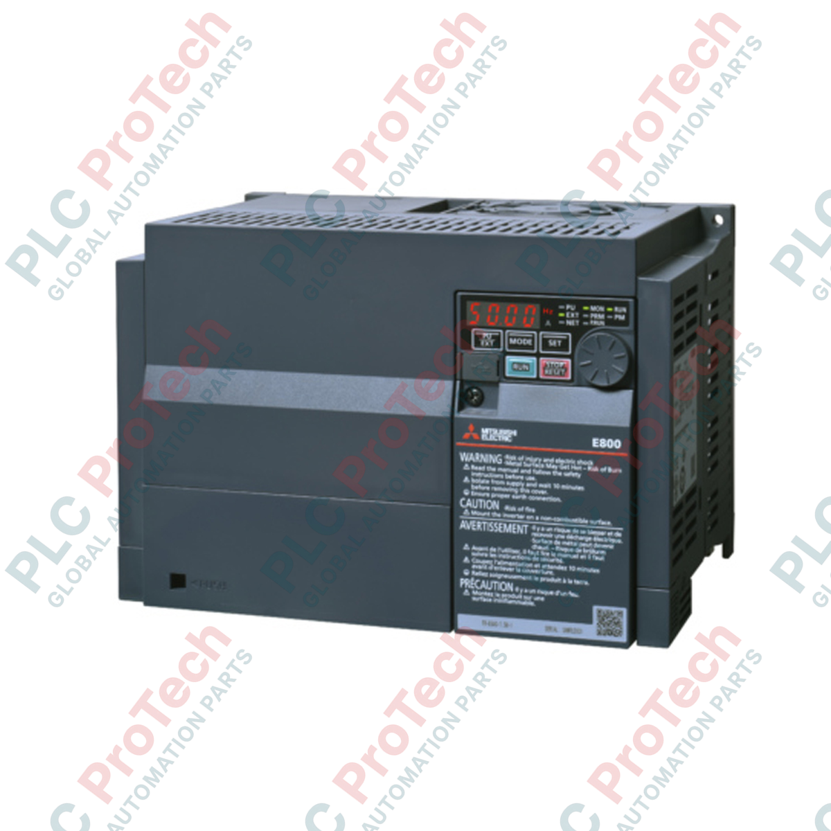
Engineered for precise speed and torque control in three-phase industrial environments, the Mitsubishi Electric FR-E840-0120-4-60 serves as a highly reliable 400V class variable frequency drive within the FR-E800 series portfolio. This compact inverter is rated for a Normal Duty (ND) current of 12.0 A, delivering robust performance under heavy cyclic loads. Designed to thrive in demanding automation settings, this unit includes standard conformally coated circuit boards to guard against atmospheric contaminants and moisture, making it an excellent match for material handling, HVAC, and pumping operations. Utilizing Source logic for its control and safety stop inputs, it integrates smoothly into standard safety-instrumented systems requiring high uptime and predictable safety response.
Key Features
-
Conformal Circuit Board Coating: Enhanced environmental protection (-60 designation) prevents corrosion and tracking faults from dust and humidity.
-
Source Logic System: Built-in Source logic for standard digital inputs and fixed Source logic for integrated safety stop signals.
-
AM Terminal Voltage Monitoring: Outfitted with an analog voltage monitoring output (Terminal AM) for real-time operation tracking.
-
Advanced Thermal Management: Compact design with built-in cooling fan optimized for tight control panel spacing.
-
Integrated Safety Stop: Supports functional safety requirements with dedicated dual-channel safety inputs to isolate motor power safely.
Industrial Applications
-
Conveyor and Logistics Systems: Smooth acceleration and deceleration control for heavy-load conveyor lines.
-
Pumping and Fan Systems: Energy-efficient variable flow and pressure regulation using built-in PID control loops.
-
Packaging Machinery: High-response speed profiles matching operational packaging sequences.
-
Textile and Material Processing: Constant tension and winding controls utilizing precise analog monitoring feedback.
Technical Specifications
| Parameter |
Specification Value |
| Manufacturer |
Mitsubishi Electric |
| Model Number |
FR-E840-0120-4-60 |
| Series Name |
FR-E800 (FR-E8) |
| Voltage Class |
400 V Class (Three-Phase Input) |
| Inverter ND Rated Current |
12.0 A |
| Rated Frequency (Initial Setting) |
50 Hz |
| Input Signal (Initial Status) |
Source logic |
| Safety Stop Signal Logic |
Source logic (Fixed) |
| Monitoring Interface |
Voltage (Terminal AM) |
| Circuit Board Coating |
Conformally coated boards (with coating) |
| Plated Conductor |
Without plated conductors |
| Cooling Type |
Forced Air Cooling |
| Net Weight |
2.4 kg |
| Shipping Weight (Calculated) |
5.0 kg |
Connections and Interfaces
| Terminal Symbol |
Terminal Name |
Description / Signal Allocation |
| R/L1, S/L2, T/L3 |
Main Circuit Power Input |
Connects to the three-phase AC power supply (380 to 480 V AC, 50 Hz / 60 Hz). |
| U, V, W |
Inverter Output Terminals |
Connects to the three-phase induction or permanent magnet motor. |
| AM |
Analog Monitor Output |
Provides analog voltage output (0 to 10 VDC) for monitoring parameter values. |
| PC |
External Transistor Common |
Acts as the 24 VDC common power supply source for digital inputs (Source logic configuration). |
| S1, S2, SIC |
Safety Input Terminals |
Used for functional safety shutdown loops (STO) in compliance with SIL2/SIL3 standards. |
Empirical Engineering Insights
Alternative Models & Compatibility
When migrating legacy systems from the older FR-E740-120-EC or FR-E740-120-NA, the newer FR-E840-0120-4-60 offers matching physical mounting dimensions but incorporates advanced safety logic and enhanced parameter groups. Be sure to backup your original parameters via FR Configurator2 software. When downloading to the FR-E840, some advanced motor constants may need manual conversion if operating older non-standard permanent magnet motors.
Application Pitfalls & Engineering Notes
Operating this inverter inside tightly enclosed, sealed panels can result in localized thermal build-ups. Ensure that surrounding clearance parameters (minimum 50 mm above and below, 20 mm on the sides) are strictly maintained to permit effective convection. When wiring safety inputs (S1 and S2), note that the safety stop terminal logic is fixed to Source logic. Attempting to use a 0V common path to control safety circuits on this specific model variant will cause hard safety interlock faults (e.g., SA status fault indication).
Commissioning & Wiring Tips
To minimize high-frequency electromagnetic interference (EMI) on the analog AM monitoring terminal, always utilize a separate shielded twisted pair (STP) cable for control signals. Ground the shield at the inverter side only, specifically to the dedicated control ground terminal. If the motor cables exceed 30 meters in length, install an output dV/dt filter or reduce the carrier frequency (Pr. 72) to prevent excessive leakage currents and premature insulation aging in the motor windings.
Installation Guidelines
CRITICAL ELECTRICAL SAFETY WARNING
Ensure the input main power line (R/L1, S/L2, T/L3) is completely de-energized and locked out before initiating any wiring or terminal access. The intermediate DC link capacitors retain dangerous electrical potential after power-off. Wait a minimum of 10 minutes following complete power disconnection, and verify that the charge indicator LED on the face of the unit is completely off before servicing terminal connections.
1
Securely mount the inverter vertically on a flat, vibration-free surface. Ensure that airflow to the heatsink fins is not obstructed by conduit runs or wire trays.
2
Route the main power lines separately from the low-voltage control lines (safety, analog output, and logic circuits) to prevent signal coupling and electromagnetic cross-talk.
3
Ensure the grounding terminal (PE) is bonded to the main system ground bus via a heavy-gauge, low-impedance conductor (minimum cross-section equivalent to power conductors).
4
Perform a continuity check on all output phases (U, V, W) to confirm that no phase-to-phase or phase-to-ground short circuits exist before powering up the drive.