Designing H-Bridge Motor Drives Without Shoot-Through
A practical guide to H-bridge motor drives covering switching states, dead time, inductive current paths, PWM choices, protection, PCB layout, PLC interfacing, and staged commissioning tests.
Manufacturer: Mitsubishi Electric
Product No.: FX2N-128MT-ES/UL
Country of origin:United States
Product Type: PLC CPU Modules
Payment: T/T, Western Union
Weight: 2800g
Dimensions: 365 mm x 125 mm x 110 mm
Shipping port: Xiamen
Warranty: 12 months
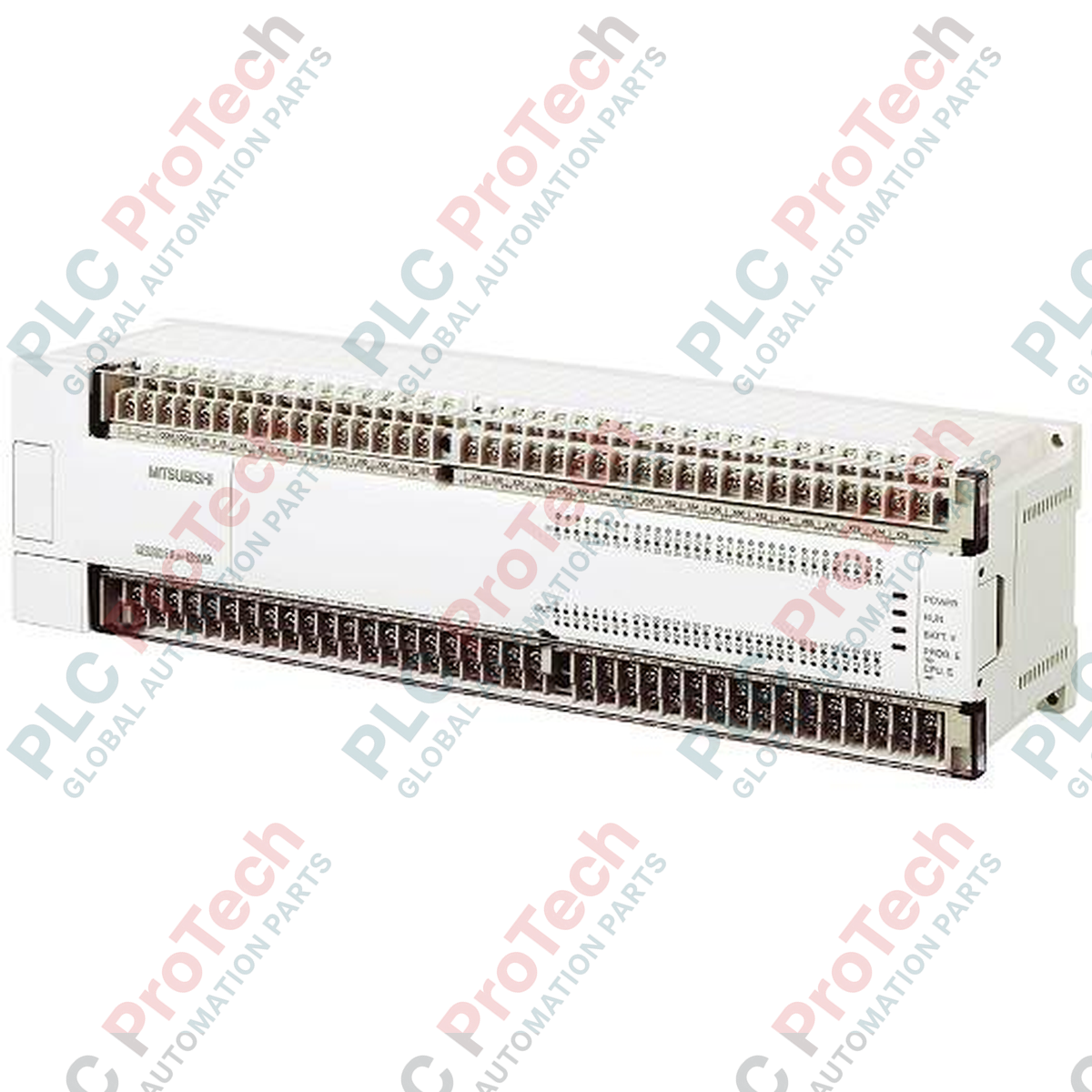
Designed for high-speed machine control and extensive local I/O integration, the Mitsubishi Electric FX2N-128MT-ES/UL serves as a high-density processing core within the MELSEC FX2N Series PLC family. This main unit features a combined total of 128 local I/O points, utilizing transistor source outputs and highly configurable sink/source inputs to manage complex automation sequences in demanding industrial environments.
| Specification Parameter | Value / Rating |
|---|---|
| Manufacturer | Mitsubishi Electric |
| Model Number | FX2N-128MT-ES/UL |
| Product Series | MELSEC FX2N |
| Rated Supply Voltage | 100 to 240V AC (50/60 Hz) |
| Power Consumption | 65W |
| Internal 24V DC Service Power | 460mA or less |
| Digital Inputs | 64 points (Sink/Source selectable, DC24V +/- 10%) |
| Digital Outputs | 64 points (Transistor / Source type, 5 to 30V DC) |
| Output Current Rating | 0.5A per point (0.8A per 4-point common, 1.6A per 8-point common) |
| Input Impedance | 3.3k Ohm (X000 to X007), 4.3k Ohm (X010 and higher) |
| Isolation Method | Photocoupler isolation |
| Connection Type | Removable terminal blocks (M3 screws) |
| Country of Origin | Japan |
| Shipping Weight (Calculated) | 1.80 kg |
| Package Dimensions (Calculated) | 365 mm x 125 mm x 110 mm |
| Terminal / Port | Functional Assignment |
|---|---|
| L, N, Ground | Main AC Power Input (100 to 240V AC) and Protective Earth |
| 24V, 0V | DC24V Service Power Output (for powering external sensors/switches) |
| S/S | Sink / Source selection terminal for digital input circuits |
| X000 to X077 | 64 Digital Input Channels (Octal numbering system) |
| Y000 to Y077 | 64 Transistor Source Output Channels (Octal numbering system) |
| +V0 to +V7 | External DC Power supply inputs for transistor output groups |
The FX2N-128MT-ES/UL is the global standard model featuring transistor source outputs. It directly replaces older Japanese-market sink-only models (such as the FX2N-128MT-D) in systems where field wiring has been updated to source logic. When migrating legacy applications to the modern MELSEC FX3U series (e.g., FX3U-128MT/ESS), program conversion can be executed via GX Works2, though physical depth and terminal block spacing must be cross-referenced to ensure panel layout compatibility.
Ensure that the cumulative current drawn from the 24V DC service power terminals does not exceed 460mA. Overloading this internal supply will cause thermal shutdown or erratic CPU behavior. Additionally, because the transistor outputs are rated for a maximum of 0.5A per single point, inductive loads such as heavy solenoids or magnetic contactors must be suppressed using external flyback diodes to prevent premature output degradation.
For high-speed counter inputs (X000 to X007), always use shielded twisted-pair cabling. Route these signal lines completely separate from high-voltage AC power lines and VFD motor cables to prevent electromagnetic interference from corrupting pulse counts. If using the built-in pulse output functions (Y000 and Y001) for positioning, verify that the external load impedance is high enough to limit current draw to 0.3A on these specific high-speed channels.
CRITICAL WARNING:
Disconnect all external power sources before attempting installation, wiring, or module replacement. Residual charges in the internal capacitors can cause electrical shock or damage sensitive internal CMOS components. Ensure the protective earth terminal is connected to a dedicated class-D ground point.
Mount the controller vertically on a standard 35mm DIN rail or directly to the backplate using the integrated mounting holes. Maintain at least 50mm of clearance above and below the unit for natural convection cooling.
Wire the AC power supply to the L and N terminals using minimum 1.25 mm² (AWG 16) conductors. Install a 5A slow-blow fuse on the hot line prior to the terminal block.
Configure the S/S terminal according to your field sensor logic: connect S/S to 24V for NPN (sink) input configurations, or to 0V for PNP (source) input configurations.
Secure all terminal screws to a torque rating of 0.5 to 0.8 N-m to prevent loose connections and potential thermal faults during operation.
Global Express Shipping
Returns & Warranty

Global Express Shipping
Returns & Warranty
Orders are processed and delivered Monday-Friday (excluding public holidays).
For full eligibility, restocking fees, and international return details, please view our official Refund & Return Policy .
| Country of origin |
United States
|