Designing H-Bridge Motor Drives Without Shoot-Through
A practical guide to H-bridge motor drives covering switching states, dead time, inductive current paths, PWM choices, protection, PCB layout, PLC interfacing, and staged commissioning tests.
Manufacturer: Mitsubishi Electric
Product No.: FX3U-80MR/DS
Country of origin:United States
Product Type: PLC CPU Modules
Payment: T/T, Western Union
Weight: 500g
Dimensions: 290 mm x 110 mm x 100 mm
Shipping port: Xiamen
Warranty: 12 months
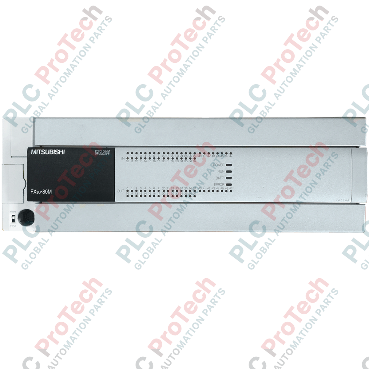
Managing complex machine-level automation architectures requires robust processing, which the Mitsubishi Electric FX3U-80MR/DS delivers as a high-performance compact PLC base unit. Engineered for industrial environments demanding high-speed execution and extensive local I/O capacity, this controller integrates 40 digital inputs and 40 relay outputs within a space-saving footprint. Operating on a 24V DC power supply, it provides the reliability and speed required for modern manufacturing, packaging, and material handling systems.
| Parameter | Specification |
|---|---|
| Manufacturer | Mitsubishi Electric |
| Model Number | FX3U-80MR/DS |
| Series | MELSEC FX3U |
| Power Supply Voltage | 24V DC (+20% / -15%) |
| Total Integrated I/O | 80 points |
| Input Specifications | 40 points, 24V DC (Sink/Source selectable) |
| Output Specifications | 40 points, Relay outputs |
| Max. Switching Capacity | 2A per point (8A per common terminal) |
| Power Consumption | 45W |
| Operating Temperature | 0 to 55 degC |
| Storage Temperature | -25 to 75 degC |
| Shipping Weight (Calculated) | 1.20 kg |
| Package Dimensions (Calculated) | 290 mm x 110 mm x 100 mm |
| Terminal / Port | Function / Circuit Assignment |
|---|---|
| L+ / M | 24V DC Main Power Input terminals |
| S/S | Input Common terminal (Connect to 24V for Sink, 0V for Source) |
| X000 - X047 | 24V DC Digital Inputs (X000 to X007 support high-speed counters) |
| Y000 - Y047 | Relay Outputs (Dry contacts) |
| COM0 - COM7 | Common return paths for relay output groups |
The FX3U-80MR/DS is the 24V DC-powered variant of this base unit. If your control cabinet utilizes AC power, the FX3U-80MR/ES (100-240V AC) is the direct physical equivalent. When migrating from older FX2N series hardware, note that while the FX3U is backward-compatible with FX2N expansion blocks, the terminal block pitch and depth differ slightly. Program conversion from FX2N to FX3U can be executed seamlessly within GX Works2, but high-speed counter and positioning instructions should be verified as the FX3U offers expanded channel capabilities.
Relay outputs are highly versatile but subject to mechanical wear. Under highly inductive loads (such as heavy-duty solenoid valves or contactor coils), the electrical life of the internal relays drops significantly. To prevent premature contact welding, always install external surge suppressors: RC snubbers for AC inductive loads, or flyback diodes for DC inductive loads. Additionally, ensure the external 24V DC power supply feeding the L+ and M terminals has a ripple factor of less than 5% to prevent intermittent CPU watchdog resets.
The S/S terminal defines the input logic for the entire block. If you are using NPN (sink) sensors, connect the S/S terminal to the 24V DC terminal. If you are using PNP (source) sensors, connect S/S to the 0V DC terminal. Mixing NPN and PNP sensors on the same base unit input group is not supported. For high-speed counter applications (X000 to X007), use shielded twisted-pair cabling and ground the shield at a single point near the PLC chassis to mitigate electromagnetic interference.
Disconnect all external power sources before attempting installation, wiring, or module replacement. Residual charge in external power supplies can cause electrical shock or permanent damage to the internal CPU circuitry. Verify that the supply voltage matches the 24V DC rating of the unit before energizing.
Mount the PLC on a standard 35mm DIN rail, ensuring the mounting clips lock securely. Maintain at least 50mm of clearance above and below the unit for natural convection cooling.
Connect the functional ground terminal to a dedicated low-impedance ground point (Class D ground, 100 ohms or less) using a minimum of 2 mm² wire.
Wire the 24V DC power supply to the L+ and M terminals. Secure all terminal screws to a torque of 0.5 to 0.8 N-m to prevent loose connections.
Configure the S/S terminal for your sensor logic (Sink or Source) before applying field power to the input circuits.
Global Express Shipping
Returns & Warranty

Global Express Shipping
Returns & Warranty
Orders are processed and delivered Monday-Friday (excluding public holidays).
For full eligibility, restocking fees, and international return details, please view our official Refund & Return Policy .
| Country of origin |
United States
|