Description
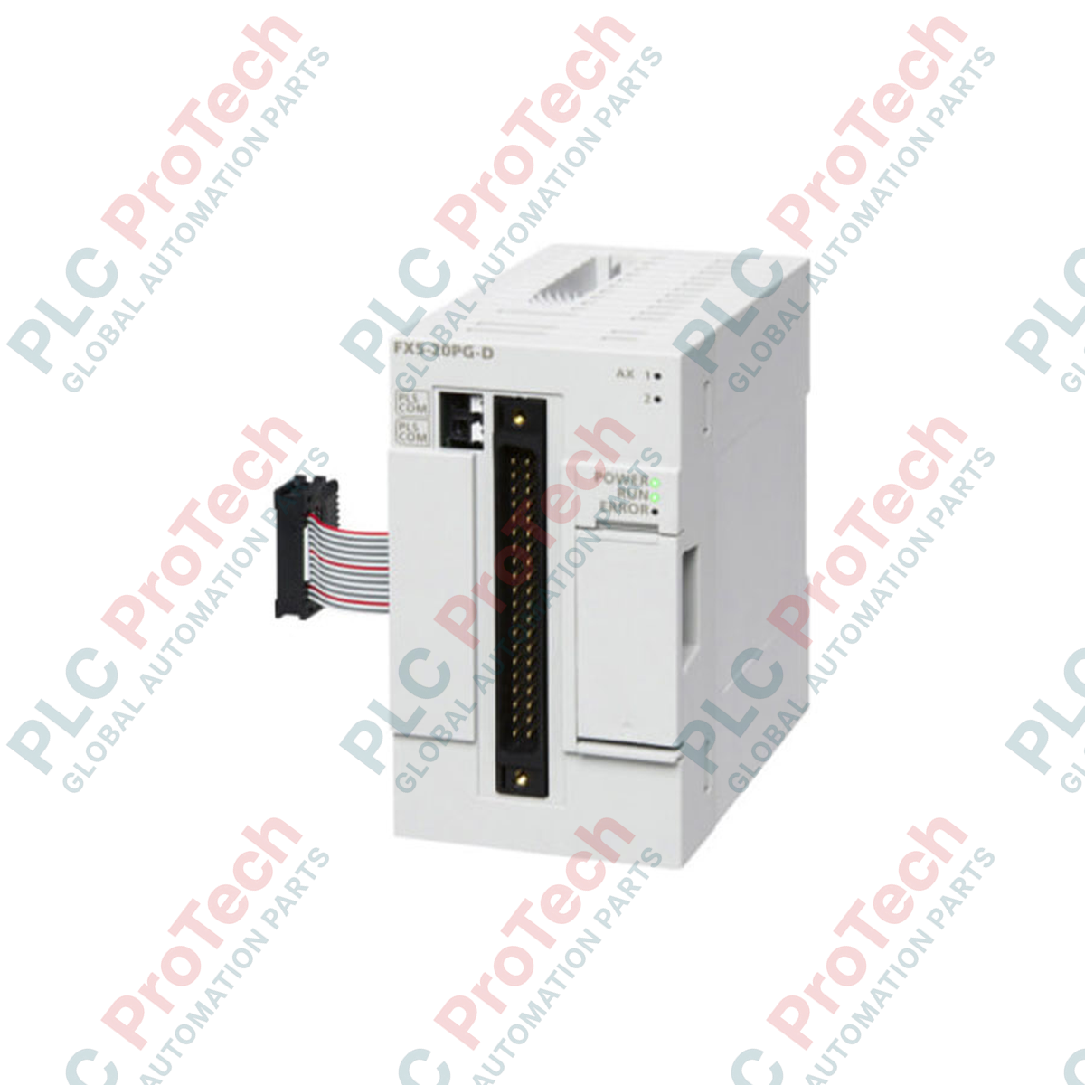
Engineered to deliver high-speed, high-precision motion control, the Mitsubishi Electric FX5-20PG-D provides dedicated 2-axis pulse train positioning capabilities within the compact MELSEC iQ-F control platform. This module features differential line driver outputs, making it ideal for noise-sensitive, high-frequency positioning tasks involving servo amplifiers and stepping motors. By offloading complex trajectory calculations from the main CPU, it ensures deterministic system response times for packaging, material handling, and assembly operations.
Features
- Independent or simultaneous 2-axis control with linear interpolation capabilities.
- Differential line driver output design for superior electrical noise immunity and extended transmission distances.
- High-speed pulse output rates up to 5 Mpps (mega-pulses per second) for ultra-precise motor indexing.
- Dedicated external inputs for limit switches, near-point dogs, and stop signals to ensure robust hardware-level positioning safety.
- Direct integration with GX Works3 software for streamlined parameter configuration and monitoring.
Applications
- High-speed multi-axis pick-and-place gantry systems.
- Form-fill-seal packaging machinery feed axes.
- Precision rotary index tables and conveyor alignment stations.
- Semiconductor material handling and positioning stages.
Technical Specifications
| Manufacturer |
Mitsubishi Electric |
| Model Reference |
FX5-20PG-D |
| Control Axes |
2 axes (independent or simultaneous) |
| Output Type |
Differential line driver |
| Maximum Pulse Rate |
5 Mpps |
| External Supply Voltage |
24 V DC (+20%, -15%) |
| Internal Current Consumption |
165 mA (at 24 V DC) |
| Input Current Rating |
5 mA |
| Input ON Current |
3 mA or more |
| Input OFF Current |
1.7 mA or less |
| Net Weight |
0.2 kg |
| Shipping Weight (Calculated) |
1.5 kg |
Empirical Engineering Insights
Alternative Models & Compatibility
The FX5-20PG-D model utilizes differential line driver outputs, which must be distinguished from the FX5-20PG-P model that uses transistor/open collector outputs. While the "-P" variation is limited to shorter physical cable runs and lower pulse speeds, the "-D" model is specifically optimized for high-speed tracking and extended wiring up to 10 meters without signal degradation. Ensure your servo amplifier or drive interfaces support differential inputs (such as RS-422 standards) before deployment.
Application Pitfalls & Engineering Notes
When routing pulse train signals at high frequencies (up to 5 Mpps), electrical noise coupling is the most frequent cause of lost steps or positional drift. Avoid routing the FX5-20PG-D output cables in parallel with high-power AC motor lines or variable frequency drive (VFD) power cables. Ensure a minimum physical separation of 100 mm inside the control cabinet, and run the signal cables in dedicated, grounded metal conduits if they must cross high-current pathways.
Commissioning & Wiring Tips
For reliable differential signal integrity, always use shielded twisted-pair (STP) cabling for the pulse and direction lines. Ground the cable shield only at the receiver end (servo amplifier chassis) to prevent ground loops. During software configuration in GX Works3, verify that the active state (pulse logic polarity) matches your drive parameter configuration; incorrect polarity setup typically manifests as immediate overtravel faults or axes moving in the opposite direction during homing sequences.
Installation Guidelines
CRITICAL WARNING
Turn off all external power supplies before mounting, wiring, or configuring the FX5-20PG-D positioning module. Failure to de-energize the entire system may cause electrical shock, driver circuit damage, or erratic, hazardous machine movements during commissioning.
1
Ensure the base PLC system (CPU and extension modules) is fully powered down and the residual charges in internal capacitors are discharged.
2
Mount the module firmly onto a standard DIN rail (DIN46277, 35 mm wide) or direct surface mount using the designated screw tabs, ensuring adequate ventilation clearances.
3
Connect the extension cable from the FX5-20PG-D to the preceding extension module or the main FX5 CPU module, securing the physical interlocking connector slide.
4
Complete signal and power wiring using high-quality terminals. Verify the external 24 V DC power supply connection matches the specified limits (+20%, -15%) before powering on the system.