


Implementing 3-Switch XOR Ladder Logic with Internal Bit
Implement a 3-SPST switch XOR light circuit in LogixPro or RSLogix 500 using an internal relay bit. Includes truth tables, boolean equations, and verified.

Designed for high-precision process control integration within the MELSEC iQ-F controller family, the FX5-4DA-ADP by Mitsubishi Electric delivers accurate digital-to-analog signal conversion across four independent channels. This compact expansion adapter mounts directly to the left side of an FX5 CPU module, converting digital numerical values into analog voltage or current signals to drive control valves, variable frequency drives, actuators, and indicators. Featuring high-resolution 14-bit processing, the unit ensures stable analog output performance in demanding electrical noise environments without consuming valuable control cabinet footprint.
| Parameter | Technical Value |
|---|---|
| Manufacturer | Mitsubishi Electric |
| Model Designation | FX5-4DA-ADP |
| Control Series | MELSEC iQ-F Series |
| Module Type | Analog Output Expansion Adapter |
| Analog Output Channels | 4 Channels |
| Analog Voltage Output Range | -10 to +10 V DC (External load resistance: 1k Ohm to 1M Ohm) |
| Analog Current Output Range | 0 to 20 mA DC, 4 to 20 mA DC (External load resistance: 0 to 350 Ohm) |
| Digital Resolution | 14-bit binary (Voltage: -8000 to +8000; Current: 0 to 8000) |
| Conversion Speed | 950 microseconds per channel |
| Internal Power Consumption | 5 V DC, 10 mA (drawn from CPU system bus) |
| External Supply Voltage | 24 V DC (+20%, -15%), 20 mA |
| Isolation Method | Optocoupler isolation (between output terminals and PLC bus); Non-isolated between channels |
| Terminal Block Connection | European-type push-in terminal block |
| Operating Temperature | -20 to +55 degC (non-freezing) |
| Country of Origin | Japan |
| Shipping Weight (Calculated) | 0.35 kg |
| Package Dimensions (Calculated) | 140 mm x 120 mm x 45 mm |
The FX5-4DA-ADP is designed specifically for FX5U and FX5UC PLC system architectures. While it shares functional characteristics with older FX3U analog blocks (like the FX3U-4DA-ADP), it utilizes a distinct system bus protocol and physical connection interface and is not backward compatible with FX3 series backplanes. When pairing the FX5-4DA-ADP with compact FX5UC CPU models, the FX5-CNV-IF conversion module is required to step down the connector format.
A common issue encountered during commissioning is channel-to-channel crosstalk or ground loops, stemming from the module's lack of inter-channel isolation. Although isolated from the CPU's internal system bus, all four output channels share a common analog return path. If you are driving field devices that reference differing electrical grounds, you must install external, loop-powered signal isolators between this adapter and the load to prevent signal offset errors and damage.
Always configure channel allocation, output signal ranges (voltage vs. current), and error-recovery behaviors (e.g., holding the last state versus dropping to clear state on CPU stop) in the GX Works3 parameter tree before powering on the system. If the external 24 V DC power supply is interrupted or cycled while the CPU is executing, the PLC will flag a hardware configuration error (Error Code 1800 series). Ensure your external power supply sequence starts concurrently with, or prior to, the PLC CPU power-up routine.
Isolate and lock out all AC and DC power sources supplying the PLC backplane and external field instruments before attempting module installation, removal, or wiring modifications. Failure to de-energize the assembly can cause fatal electrical shock, permanently corrupt CPU system firmware, or damage internal solid-state components.
Remove the protective extension connector cover located on the left side of the CPU module or the preceding expansion adapter.
Carefully align the slide locks and system connector of the FX5-4DA-ADP with the mating interfaces of the CPU, then press them firmly together until they click into place.
Slide the lock mechanism on both top and bottom corners to secure the physical connection lock.
Connect the external 24 V DC power cables and standard shielded twisted-pair analog signal cables, ensuring the shield drains are terminated to functional ground (Class D, 100 Ohm or less) at a single end.
Global Express Shipping
Returns & Warranty


Manufacturer: Mitsubishi Electric
Product No.: FX5-4DA-ADP
Country of origin:United States
Product Type: PLC Analog Output Modules
Payment: T/T, Western Union
Weight: 1500g
Dimensions: 140 mm x 120 mm x 45 mm
Shipping port: Xiamen
Warranty: 12 months
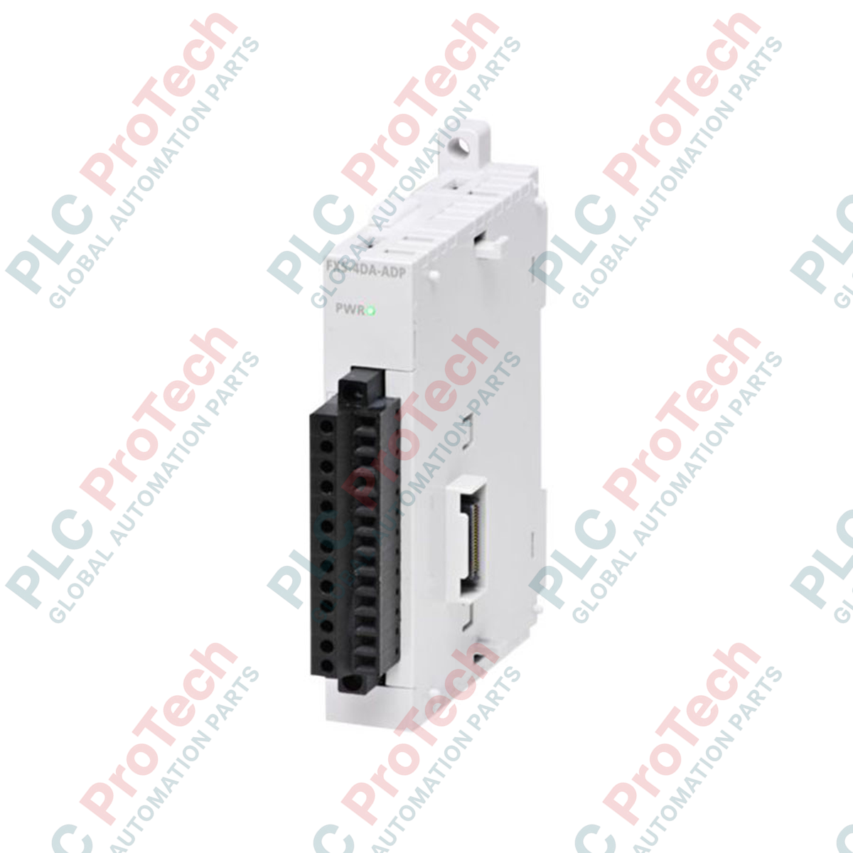
Designed for high-precision process control integration within the MELSEC iQ-F controller family, the FX5-4DA-ADP by Mitsubishi Electric delivers accurate digital-to-analog signal conversion across four independent channels. This compact expansion adapter mounts directly to the left side of an FX5 CPU module, converting digital numerical values into analog voltage or current signals to drive control valves, variable frequency drives, actuators, and indicators. Featuring high-resolution 14-bit processing, the unit ensures stable analog output performance in demanding electrical noise environments without consuming valuable control cabinet footprint.
| Parameter | Technical Value |
|---|---|
| Manufacturer | Mitsubishi Electric |
| Model Designation | FX5-4DA-ADP |
| Control Series | MELSEC iQ-F Series |
| Module Type | Analog Output Expansion Adapter |
| Analog Output Channels | 4 Channels |
| Analog Voltage Output Range | -10 to +10 V DC (External load resistance: 1k Ohm to 1M Ohm) |
| Analog Current Output Range | 0 to 20 mA DC, 4 to 20 mA DC (External load resistance: 0 to 350 Ohm) |
| Digital Resolution | 14-bit binary (Voltage: -8000 to +8000; Current: 0 to 8000) |
| Conversion Speed | 950 microseconds per channel |
| Internal Power Consumption | 5 V DC, 10 mA (drawn from CPU system bus) |
| External Supply Voltage | 24 V DC (+20%, -15%), 20 mA |
| Isolation Method | Optocoupler isolation (between output terminals and PLC bus); Non-isolated between channels |
| Terminal Block Connection | European-type push-in terminal block |
| Operating Temperature | -20 to +55 degC (non-freezing) |
| Country of Origin | Japan |
| Shipping Weight (Calculated) | 0.35 kg |
| Package Dimensions (Calculated) | 140 mm x 120 mm x 45 mm |
The FX5-4DA-ADP is designed specifically for FX5U and FX5UC PLC system architectures. While it shares functional characteristics with older FX3U analog blocks (like the FX3U-4DA-ADP), it utilizes a distinct system bus protocol and physical connection interface and is not backward compatible with FX3 series backplanes. When pairing the FX5-4DA-ADP with compact FX5UC CPU models, the FX5-CNV-IF conversion module is required to step down the connector format.
A common issue encountered during commissioning is channel-to-channel crosstalk or ground loops, stemming from the module's lack of inter-channel isolation. Although isolated from the CPU's internal system bus, all four output channels share a common analog return path. If you are driving field devices that reference differing electrical grounds, you must install external, loop-powered signal isolators between this adapter and the load to prevent signal offset errors and damage.
Always configure channel allocation, output signal ranges (voltage vs. current), and error-recovery behaviors (e.g., holding the last state versus dropping to clear state on CPU stop) in the GX Works3 parameter tree before powering on the system. If the external 24 V DC power supply is interrupted or cycled while the CPU is executing, the PLC will flag a hardware configuration error (Error Code 1800 series). Ensure your external power supply sequence starts concurrently with, or prior to, the PLC CPU power-up routine.
Isolate and lock out all AC and DC power sources supplying the PLC backplane and external field instruments before attempting module installation, removal, or wiring modifications. Failure to de-energize the assembly can cause fatal electrical shock, permanently corrupt CPU system firmware, or damage internal solid-state components.
Remove the protective extension connector cover located on the left side of the CPU module or the preceding expansion adapter.
Carefully align the slide locks and system connector of the FX5-4DA-ADP with the mating interfaces of the CPU, then press them firmly together until they click into place.
Slide the lock mechanism on both top and bottom corners to secure the physical connection lock.
Connect the external 24 V DC power cables and standard shielded twisted-pair analog signal cables, ensuring the shield drains are terminated to functional ground (Class D, 100 Ohm or less) at a single end.
Global Express Shipping
Returns & Warranty
Orders are processed and delivered Monday-Friday (excluding public holidays).
For full eligibility, restocking fees, and international return details, please view our official Refund & Return Policy .
| Country of origin |
United States
|

Implement a 3-SPST switch XOR light circuit in LogixPro or RSLogix 500 using an internal relay bit. Includes truth tables, boolean equations, and verified.

Integrate Allen-Bradley CompactLogix, Caterpillar ATS, and generators into DeltaV DCS over Modbus RTU. Covers ProSoft MVI69-MCM, Miille DIN266 gateways.

ONS instruction fires but the OTE coil never latches in Studio 5000 because the one-shot is only true for one scan. Use OTL/OTU or seal-in logic instead.

Configure Allen-Bradley Kinetix 5500 servo drives on EtherNet/IP. Covers CIP Sync, IEEE 1588 V2 timing, Stratix selection, DLR topology, and HMI.

A moving-average filter is the sliding-window smoother most instrument engineers drop into DCS and PLC analog paths. Here is how the window works, how N and sample time set lag, and when a...

On Frame 5–9 gas turbines, GE Mark VI and Mark VIe run control as function-block application software. This article maps process, protection, and sequencing functions—and what Toolbox ST access...