Description
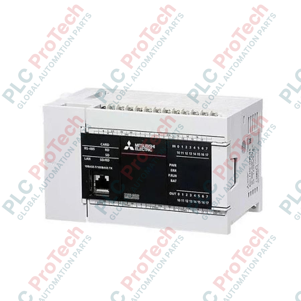
Integrating advanced sequential and analog control into a compact form factor, the Mitsubishi Electric FX5U-32MT/DS-TS acts as the primary processing node for the MELSEC iQ-F controller platform. This CPU module features 32 integrated I/O channels (16 inputs, 16 outputs) equipped with Tension Spring (TS) terminal blocks, offering exceptional wiring speed and field reliability in high-vibration industrial settings. Operable on a 24V DC power supply, it integrates dual-port analog inputs, single-port analog output, high-speed counters, and multi-axis positioning interfaces without requiring additional expansion cards. Its execution speeds, coupled with built-in Ethernet and RS-485 ports, make it highly suited for modern, networked manufacturing architectures.
Features
-
Vibration-Proof Connections: Tension spring-clamp terminals eliminate screw-loosening risks and reduce field wiring installation times.
-
High-Speed Processing: Extremely fast basic instruction execution speeds of 34 nanoseconds optimize system response.
-
Built-In Communication: Integrates an Ethernet port for network integration and an RS-485 port for Modbus and dedicated inverter control.
-
Embedded Analog Capabilities: Features 2 channels of 12-bit analog input (0 to 10V DC) and 1 channel of analog output (0 to 10V DC).
-
Positioning Capabilities: Built-in high-speed counters up to 200 kHz and multi-axis positioning outputs for motion control applications.
-
Secure Data Management: Built-in SD memory card slot supports data logging, firmware updates, and simple project transfers.
Applications
- High-vibration assembly and packaging systems
- Conveyor tracking and automated material handling sorting
- Automated dosing, pumping, and chemical treatment skids
- Multi-axis pick-and-place assembly stations
Technical Specifications Table
| Parameter |
Specification Value |
| Manufacturer |
Mitsubishi Electric |
| Model Number |
FX5U-32MT/DS-TS |
| Controller Series |
MELSEC iQ-F |
| Power Supply Voltage |
24 V DC (+20%, -15%) |
| Integrated Inputs |
16 Points (24 V DC, Sink/Source, 5.3 mA) |
| Integrated Outputs |
16 Points (Transistor, Sink Type) |
| Terminal Type |
Tension Spring (Spring Clamp) Terminals |
| Analog Inputs |
2 Channels (0 to 10 V DC, 12-bit conversion) |
| Analog Outputs |
1 Channel (0 to 10 V DC, 12-bit conversion) |
| Memory Capacity |
64k Steps Program Memory, 512k Words Data Memory |
| Built-in Comm Ports |
Ethernet (100Base-TX), RS-485 (Terminal) |
| Operating Temperature |
0 to 55 degC |
| Shipping Weight (Calculated) |
0.85 kg |
| Package Dimensions (Calculated) |
150 x 120 x 110 mm |
Connections and Interfaces
| Terminal Group |
Assignment & Function |
| Power Supply |
24V DC (+), 24V DC (-), Functional Ground (FG) |
| Digital Inputs (X0 - X17) |
24V DC optocoupler-isolated inputs, sink/source configurable via common terminal |
| Digital Outputs (Y0 - Y17) |
Transistor outputs, sink type (common terminal connected to 0V) |
| Analog Inputs (V1+, V2+, V-) |
2 channels of voltage inputs (0 to 10V DC) sharing a common return channel |
| Analog Output (Vout, Iout) |
1 channel of analog output supporting voltage mode (0 to 10V DC) |
Alternative Models & Compatibility
The FX5U-32MT/DS-TS can directly replace standard FX5U-32MT/DS models in terms of processing logic, firmware, and functional execution. However, the "-TS" suffix specifies tension spring terminals instead of the screw-terminal design on standard models. This physical difference requires matching wiring termination preparation (using solid core or correctly rated wire ferrules without crimping tools on insertion). Program files written in GX Works3 are completely cross-compatible between both physical termination versions.
Application Pitfalls & Engineering Notes
Since this CPU has a DC transistor sink-type output configuration, you must ensure that all inductive external loads (such as DC relays and solenoid valves) are properly installed with protective freewheeling diodes to prevent voltage kickback damage to the outputs. For thermal management inside closed control cabinets, a minimum space of 50 mm must be maintained above and below the module to ensure natural convection. Avoid running high-voltage AC cables alongside the low-voltage DC terminal lines inside the same ducting to prevent signal corruption.
Commissioning & Wiring Tips
When utilizing the built-in analog inputs and outputs, ensure that double-shielded twisted pair cables are used and that the shield is grounded only at a single, clean grounding point. The integrated spring-clamp terminals accept a wire cross-section of 0.2 to 1.5 mm² (AWG 24 to 16). Do not twist stranded wire ends before insertion unless they are terminated with a proper, uninsulated or insulated ferrule. A standard flathead screwdriver with a blade width of 2.0 to 2.5 mm is required to open the spring clamping mechanism for wire extraction.
Installation Guidelines
CRITICAL WARNING
Isolate all electrical power sources before mounting, dismantling, or servicing the unit. Failure to fully de-energize the incoming supply panel may result in serious electrical shock, hardware destruction, or erratic output switching states.
1
Snap the CPU module securely onto a standard 35 mm DIN rail or install it directly onto the backplate using the integrated mounting screw holes.
2
Verify that the 24V DC incoming feed is off, then terminate the power supply cables (+ and -) into the designated power terminals.
3
Using a suitable flat screwdriver, gently actuate the spring-clamp mechanisms to insert the control, I/O, and analog signal lines.
4
Verify ground terminal integrity by ensuring the Functional Ground (FG) is connected to the central cabinet earth grounding bar.