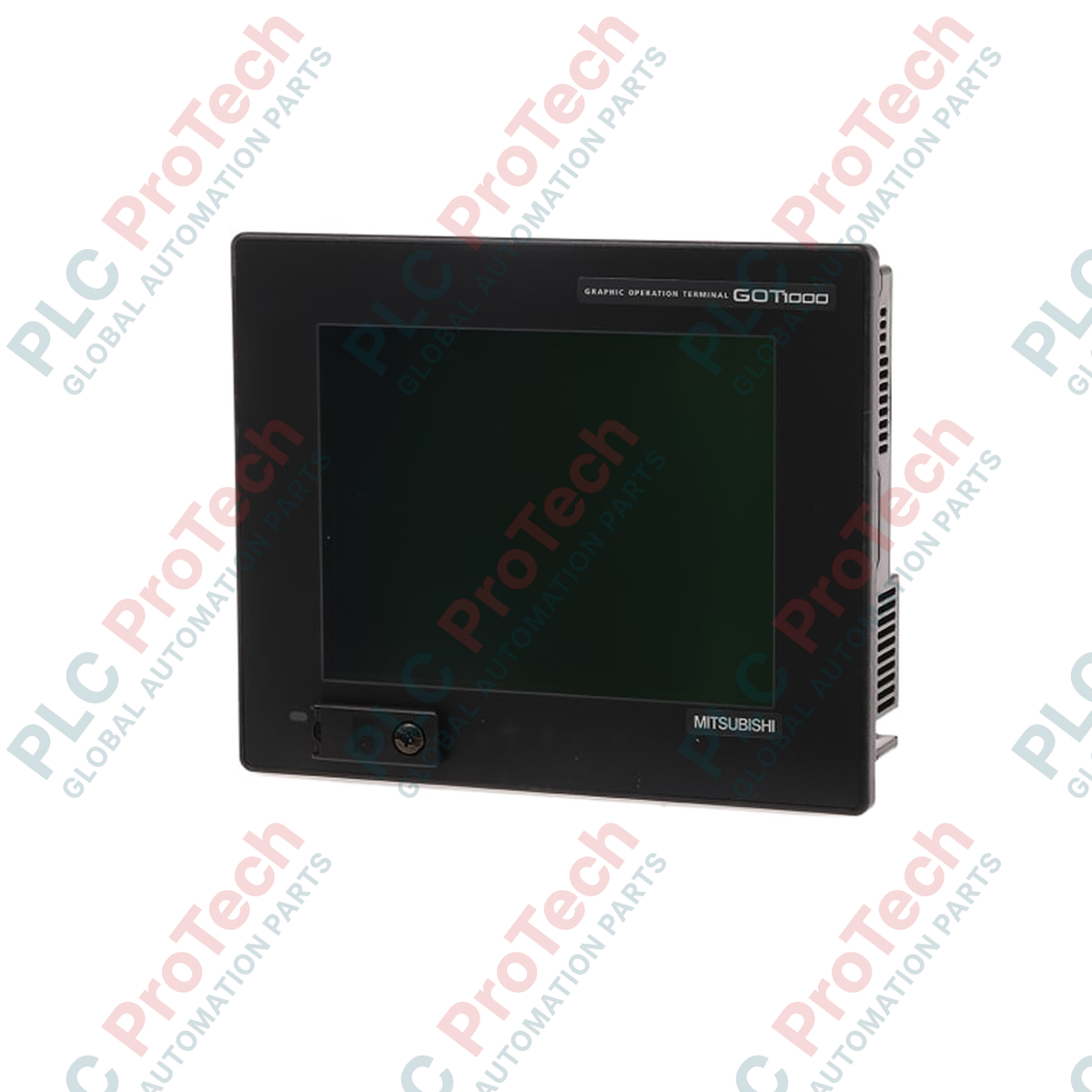
Designed to serve as a robust human-machine interface within industrial control networks, the Mitsubishi Electric GT1265-VNBA provides high-resolution visualization and operator control for automated machinery. This GOT1000 Series terminal features an 8.4-inch TFT color LCD display with a resolution of 640 x 480 pixels, delivering clear graphical representation of machine states, alarms, and real-time process data.
Key Features
- 8.4-inch TFT color display supporting up to 256 colors for clear diagnostic visualization.
- Analog resistive touch panel allowing flexible, high-density key layouts.
- Replaceable cold-cathode fluorescent tube (CCFL) backlight for extended service life.
- Built-in communication interfaces for seamless PLC and peripheral integration.
- Compact physical footprint with a depth of only 58 mm, ideal for shallow control enclosures.
Industrial Applications
- Automotive assembly lines and robotic work cells.
- Packaging machinery and automated material handling systems.
- Water treatment facilities and pump control stations.
- Food and beverage processing control panels.
Technical Specifications
| Parameter |
Specification |
| Display Type |
TFT Color LCD |
| Screen Size |
8.4 inches |
| Resolution |
640 x 480 dots |
| Display Colors |
256 colors |
| Effective Display Area |
170.9 (W) x 128.2 (H) mm |
| Touch Panel Type |
Analog resistive (minimum 2 x 2 dots per key) |
| Backlight |
Replaceable CCFL (1 tube) |
| Input Voltage |
100 to 240 V AC (+10%, -15%) |
| Power Consumption |
41 VA or less |
| External Dimensions |
241 (W) x 190 (H) x 58 (D) mm |
| Panel Cut Dimensions |
227 (W) x 176 (H) mm |
| Operating Temperature |
0 to 50 degC |
| Storage Temperature |
-20 to 60 degC |
| Protection Rating |
IP67f (front panel when mounted) |
| Net Weight |
1.7 kg |
| Shipping Weight |
8.0 kg (including protective packaging) |
| Manufacturer |
Mitsubishi Electric |
| Country of Origin |
Japan |
Connections and Interfaces
| Interface Port |
Function / Assignment |
| RS-232 |
Connection to PLC, PC, or serial printer (9-pin D-sub male) |
| RS-422/485 |
Connection to PLC or controller (9-pin D-sub female) |
| USB Device |
Mini-B port for screen data transfer and OS installation |
| USB Host |
Type-A port for USB memory storage devices |
| Power Input |
L, N, and Ground screw terminals (100-240V AC) |
Empirical Engineering Insights
Alternative Models & Compatibility
The GT1265-VNBA is a key component of the legacy GOT1000 platform. When migrating from older GOT900 series terminals, screen projects can be converted using Mitsubishi GT Works3 software. For modern system upgrades, the GT2508 series serves as the direct functional successor, offering enhanced processing speeds and capacitive multi-touch displays.
Application Pitfalls & Engineering Notes
The CCFL backlight in this unit has a nominal operating life of approximately 50,000 hours before brightness drops to 50%. In high-temperature environments exceeding 40 degC, backlight degradation accelerates. Ensure the enclosure has adequate ventilation to maintain the internal panel temperature below 50 degC.
Commissioning & Wiring Tips
To prevent communication dropouts and electrical noise interference on the RS-422/485 serial lines, always use shielded twisted-pair cabling. Connect the terminal's functional ground (FG) to a dedicated Class D ground (100 ohms or less resistance) and ensure it is physically isolated from high-current motor drive grounds.
Installation Guidelines
CRITICAL WARNING
Before starting installation, mounting, or wiring, ensure all external power sources feeding the HMI and connected PLCs are completely de-energized. Failure to isolate power can result in severe electrical shock, hardware damage, or erratic system startup.
1
Prepare the panel cutout matching the exact dimensions of 227 mm x 176 mm. Ensure the mounting surface is flat and free of burrs.
2
Verify that the waterproof packing gasket is correctly seated in the groove on the rear of the HMI bezel to maintain the IP67f protection rating.
3
Insert the HMI unit through the panel cutout from the front side.
4
Attach the supplied mounting brackets to the slots on the top and bottom of the unit. Tighten the mounting screws to the specified torque (0.36 to 0.48 N-m) to ensure uniform sealing without warping the bezel.
5
Connect the power supply wiring to the terminal block, ensuring the ground terminal is properly bonded to the panel chassis.