


Implementing 3-Switch XOR Ladder Logic with Internal Bit
Implement a 3-SPST switch XOR light circuit in LogixPro or RSLogix 500 using an internal relay bit. Includes truth tables, boolean equations, and verified.

Providing high-speed Ethernet connectivity directly to MELSEC L Series architectures, the Mitsubishi Electric LJ71E71-100-CM manages robust plant-level data transmission and programming tasks. This module enables fast, reliable industrial network communications by acting as a gateway between the processor unit and supervisor-level SCADA systems, HMIs, or other controllers. Featuring dual-rate physical media support for 100BASE-TX and 10BASE-T networks, the module seamlessly processes intensive data payloads while maintaining low internal bus current draw. Built-in system functions allow for easy remote maintenance, diagnostic monitoring, and configuration changes directly through the GX Works2 programming software platform.
| Manufacturer | Mitsubishi Electric |
| Model Number | LJ71E71-100-CM |
| Product Series | MELSEC L Series |
| Module Type | Ethernet Interface Module |
| Data Transmission Speed | 100 Mbps (100BASE-TX) / 10 Mbps (10BASE-T) |
| Communication Port Type | RJ45 female connector |
| Internal Current Consumption (5 VDC) | 0.60 A |
| Max Simultaneous Connections | 16 connections |
| Shipping Weight (Calculated) | 0.45 kg |
| Package Dimensions (Calculated) | 130 mm x 110 mm x 45 mm |
| Connector Pin | Function / Assignment |
|---|---|
| Pin 1 | TX+ (Transmit Data +) |
| Pin 2 | TX- (Transmit Data -) |
| Pin 3 | RX+ (Receive Data +) |
| Pin 6 | RX- (Receive Data -) |
The LJ71E71-100-CM is physically and functionally drop-in compatible with standard MELSEC L Series CPU systems. The "-CM" suffix indicates regional industrial standard compliance configurations, though identical Ethernet configurations apply inside GX Works2. In legacy migrations, verify your CPU unit firmware supports multi-connection network interfaces before integrating this module to prevent communication timeout faults.
When adding the Ethernet module to an active L-Series CPU stack, recalculate your internal 5 VDC system bus current draw. This unit draws a constant 0.60 A. If combined with multiple positioning modules or high-density digital I/O blocks, you may exceed the current supply limit of standard power modules (such as the L61P or L63P), which can cause random CPU lockups or system reset faults.
To prevent high-frequency EMI noise from adjacent high-voltage machinery or VFD cabling from disrupting network communication packets, always use Category 5e (or higher) double-shielded twisted pair (STP) cables. Securely connect the cable shielding mesh directly to the system's protective ground bus and establish a single-point earth ground for the rack assembly.
Disconnect all external power sources supplying the PLC system and network interfaces before inserting, removing, or wiring the communication module. Failure to completely de-energize the assembly can cause permanent backplane circuit damage, microprocessor failure, or unpredictable system behavior.
Align the module's locking hook with the adjacent CPU module or base unit connector slot on the DIN rail.
Press the modules together until they click firmly, and securely engage the mechanical locking levers at the top and bottom of the unit.
Insert the RJ45 industrial Ethernet cable into the front communication port, ensuring the locking clip latches securely.
Apply power and verify that the front panel LED indicators display "RUN" and the Link/Speed indicators flash on network activity.
Global Express Shipping
Returns & Warranty


Manufacturer: Mitsubishi Electric
Product No.: LJ71E71-100-CM
Country of origin:United States
Product Type: PLC Communication Modules
Payment: T/T, Western Union
Weight: 2000g
Dimensions: 130 mm x 110 mm x 45 mm
Shipping port: Xiamen
Warranty: 12 months
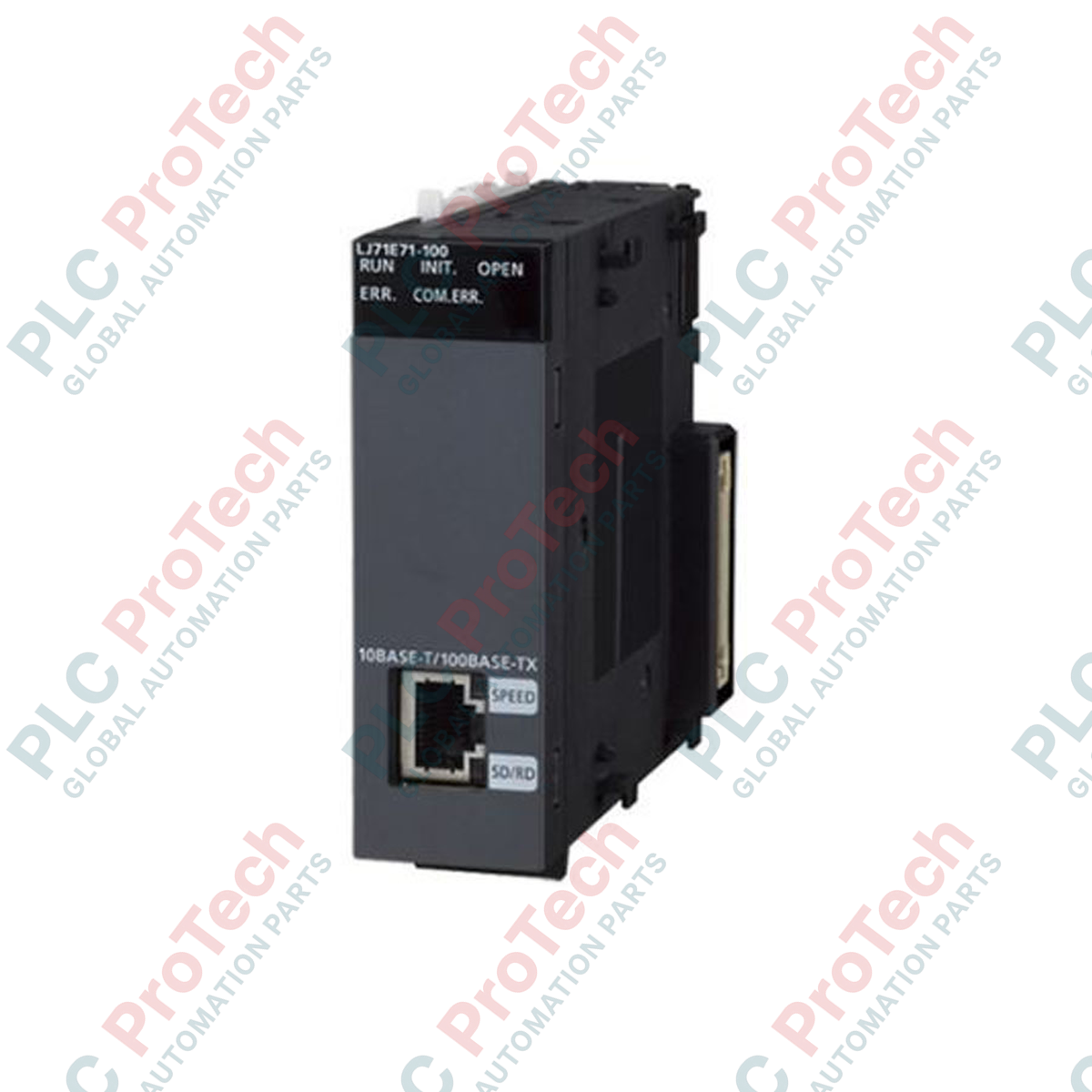
Providing high-speed Ethernet connectivity directly to MELSEC L Series architectures, the Mitsubishi Electric LJ71E71-100-CM manages robust plant-level data transmission and programming tasks. This module enables fast, reliable industrial network communications by acting as a gateway between the processor unit and supervisor-level SCADA systems, HMIs, or other controllers. Featuring dual-rate physical media support for 100BASE-TX and 10BASE-T networks, the module seamlessly processes intensive data payloads while maintaining low internal bus current draw. Built-in system functions allow for easy remote maintenance, diagnostic monitoring, and configuration changes directly through the GX Works2 programming software platform.
| Manufacturer | Mitsubishi Electric |
| Model Number | LJ71E71-100-CM |
| Product Series | MELSEC L Series |
| Module Type | Ethernet Interface Module |
| Data Transmission Speed | 100 Mbps (100BASE-TX) / 10 Mbps (10BASE-T) |
| Communication Port Type | RJ45 female connector |
| Internal Current Consumption (5 VDC) | 0.60 A |
| Max Simultaneous Connections | 16 connections |
| Shipping Weight (Calculated) | 0.45 kg |
| Package Dimensions (Calculated) | 130 mm x 110 mm x 45 mm |
| Connector Pin | Function / Assignment |
|---|---|
| Pin 1 | TX+ (Transmit Data +) |
| Pin 2 | TX- (Transmit Data -) |
| Pin 3 | RX+ (Receive Data +) |
| Pin 6 | RX- (Receive Data -) |
The LJ71E71-100-CM is physically and functionally drop-in compatible with standard MELSEC L Series CPU systems. The "-CM" suffix indicates regional industrial standard compliance configurations, though identical Ethernet configurations apply inside GX Works2. In legacy migrations, verify your CPU unit firmware supports multi-connection network interfaces before integrating this module to prevent communication timeout faults.
When adding the Ethernet module to an active L-Series CPU stack, recalculate your internal 5 VDC system bus current draw. This unit draws a constant 0.60 A. If combined with multiple positioning modules or high-density digital I/O blocks, you may exceed the current supply limit of standard power modules (such as the L61P or L63P), which can cause random CPU lockups or system reset faults.
To prevent high-frequency EMI noise from adjacent high-voltage machinery or VFD cabling from disrupting network communication packets, always use Category 5e (or higher) double-shielded twisted pair (STP) cables. Securely connect the cable shielding mesh directly to the system's protective ground bus and establish a single-point earth ground for the rack assembly.
Disconnect all external power sources supplying the PLC system and network interfaces before inserting, removing, or wiring the communication module. Failure to completely de-energize the assembly can cause permanent backplane circuit damage, microprocessor failure, or unpredictable system behavior.
Align the module's locking hook with the adjacent CPU module or base unit connector slot on the DIN rail.
Press the modules together until they click firmly, and securely engage the mechanical locking levers at the top and bottom of the unit.
Insert the RJ45 industrial Ethernet cable into the front communication port, ensuring the locking clip latches securely.
Apply power and verify that the front panel LED indicators display "RUN" and the Link/Speed indicators flash on network activity.
Global Express Shipping
Returns & Warranty
Orders are processed and delivered Monday-Friday (excluding public holidays).
For full eligibility, restocking fees, and international return details, please view our official Refund & Return Policy .
| Country of origin |
United States
|

Implement a 3-SPST switch XOR light circuit in LogixPro or RSLogix 500 using an internal relay bit. Includes truth tables, boolean equations, and verified.

Integrate Allen-Bradley CompactLogix, Caterpillar ATS, and generators into DeltaV DCS over Modbus RTU. Covers ProSoft MVI69-MCM, Miille DIN266 gateways.

ONS instruction fires but the OTE coil never latches in Studio 5000 because the one-shot is only true for one scan. Use OTL/OTU or seal-in logic instead.

Configure Allen-Bradley Kinetix 5500 servo drives on EtherNet/IP. Covers CIP Sync, IEEE 1588 V2 timing, Stratix selection, DLR topology, and HMI.

A moving-average filter is the sliding-window smoother most instrument engineers drop into DCS and PLC analog paths. Here is how the window works, how N and sample time set lag, and when a...

On Frame 5–9 gas turbines, GE Mark VI and Mark VIe run control as function-block application software. This article maps process, protection, and sequencing functions—and what Toolbox ST access...