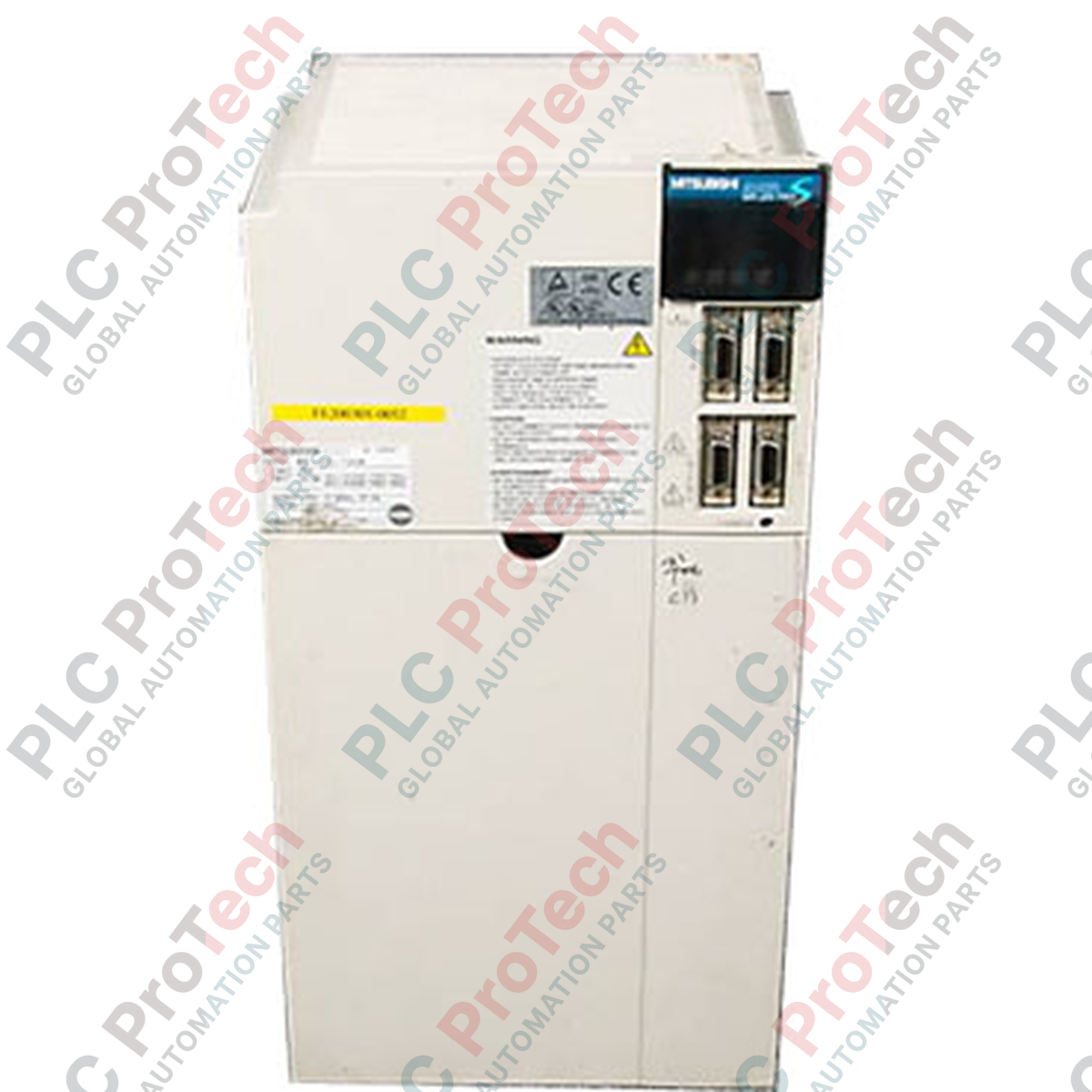
Designed for high-precision motion control, the Mitsubishi Electric MR-J2S-700B AC servo amplifier delivers reliable closed-loop performance within the MELSERVO J2S Series ecosystem. This unit integrates seamlessly with motion controllers via the high-speed SSCNET serial bus interface, providing synchronous control for complex multi-axis industrial machinery.
Key Features
-
SSCNET Bus Compatibility: Enables high-speed, noise-immune fiber optic communication with motion controllers.
-
Sinusoidal PWM Control: Optimizes current delivery to the servomotor, reducing torque ripple and heat generation.
-
Built-In Dynamic Brake: Provides rapid deceleration and emergency stopping capabilities to protect mechanical components.
-
Comprehensive Protection: Features integrated diagnostics for overcurrent, regeneration overvoltage, overload, and encoder communication faults.
-
Active Cooling: Equipped with an internal cooling fan to maintain stable operating temperatures under high-duty cycles.
Applications
- Multi-axis CNC machining centers and precision metalworking machinery.
- Automated packaging systems and high-speed bottling lines.
- Semiconductor manufacturing equipment and robotic pick-and-place systems.
- Material handling gantries and automated storage/retrieval systems (ASRS).
Technical Specifications
| Parameter |
Specification |
| Manufacturer |
Mitsubishi Electric |
| Model Number |
MR-J2S-700B |
| Series |
MELSERVO-J2-Super (MELSERVO J2S) |
| Input Power Supply |
3-phase 200-230 VAC, 50/60 Hz |
| Permissible Voltage Fluctuation |
3-phase 170-253 VAC |
| Permissible Frequency Fluctuation |
+/- 5% |
| Control Method |
Sinusoidal PWM control / current control system |
| Speed Frequency Response |
550 Hz or more |
| Dynamic Brake |
Built-in |
| Enclosure Rating |
IP00 (Open type, requires control panel installation) |
| Cooling Method |
Forced fan cooling |
| Operating Temperature |
0 to 55 degC (non-freezing) |
| Storage Temperature |
-20 to 65 degC (non-freezing) |
| Ambient Humidity |
90% RH maximum (non-condensing) |
| Maximum Elevation |
1000m or less above sea level |
| Vibration Resistance |
5.9 m/s sq. maximum |
| Shipping Weight |
8.2 kg |
Connections and Interfaces
| Terminal / Connector |
Function / Assignment |
| L1 / L2 / L3 |
3-phase AC main power supply input |
| L11 / L21 |
Control circuit power supply input |
| U / V / W |
Servo motor power output connection |
| CN1A / CN1B |
SSCNET bus connection ports (for system daisy-chaining) |
| CN2 |
Encoder feedback connection port |
Empirical Engineering Insights
Alternative Models & Compatibility
The MR-J2S-700B utilizes the SSCNET protocol, making it incompatible with the analog/pulse-train MR-J2S-700A variant. When replacing older MR-J2-700B units, ensure that the controller firmware supports the updated parameter set of the J2S series.
Application Pitfalls & Engineering Notes
Because this unit is rated IP00, it must be installed in a clean, dust-free control cabinet (IP54 or better). In high-inertia applications, the internal regenerative resistor may overheat. If the amplifier frequently trips on regenerative overvoltage (AL.30) or regenerative overload (AL.37), an external regenerative option must be wired to terminals P and C, with the shorting bar between P and D removed.
Commissioning & Wiring Tips
Always use genuine Mitsubishi fiber optic cables for the CN1A/CN1B ports. Ensure the minimum bending radius of the fiber optic cable is strictly maintained to prevent signal attenuation, which leads to intermittent communication faults (AL.85). Ground the amplifier chassis directly to the main panel backplate using a short, thick braid to minimize high-frequency EMI.
Installation Guidelines
CRITICAL WARNING
Ensure all input power sources (main and control circuits) are completely de-energized before attempting installation, wiring, or maintenance. Wait at least 10 minutes after power-off for the internal bus capacitors to discharge. Verify that the charge lamp on the front face of the amplifier is completely extinguished before touching any terminals.
1
Mount the servo amplifier vertically on a flat, rigid surface inside the control panel, ensuring adequate clearance around the cooling fan intakes and exhaust ports.
2
Connect the protective earth (PE) terminal to the system ground before making any other electrical connections.
3
Wire the main 3-phase power supply to terminals L1, L2, and L3, and the control power supply to L11 and L21.
4
Connect the motor power cables to terminals U, V, and W, and plug the encoder cable into the CN2 port.
5
Insert the SSCNET fiber optic cables into CN1A and CN1B, ensuring they click securely into place.