


Implementing 3-Switch XOR Ladder Logic with Internal Bit
Implement a 3-SPST switch XOR light circuit in LogixPro or RSLogix 500 using an internal relay bit. Includes truth tables, boolean equations, and verified.

Operating on a 200V class supply, the Mitsubishi Electric MR-J4-10A single-axis servo drive is engineered to deliver highly responsive closed-loop motion control for 0.1 kW rotary, linear, and direct-drive motors within the MELSERVO-J4 automation platform. This unit interfaces seamlessly via a general-purpose command interface, accommodating both high-speed pulse train train positioning and analog speed or torque control methods. Equipped with 22-bit high-resolution encoder feedback, it achieves remarkable micro-positioning precision. Its robust diagnostic suite and integrated Safe Torque Off (STO) safety mechanisms ensure high reliability and compliance in demanding industrial system designs.
| Specification Parameter | Value / Rating |
|---|---|
| Manufacturer | Mitsubishi Electric |
| Model / SKU | MR-J4-10A |
| Series | MELSERVO-J4 |
| Output Rated Power | 0.1 kW (100 W) |
| Output Voltage / Current | Three-phase 170 V AC / 1.1 A |
| Main Circuit Supply Input | Single-phase or Three-phase 200 V AC to 240 V AC, 50/60 Hz |
| Allowable Input Voltage Fluctuation | 170 V AC to 264 V AC |
| Control Circuit Supply Input | Single-phase 200 V AC to 240 V AC, 50/60 Hz (0.2 A to 0.3 A) |
| Control System | Sinusoidal wave PWM control and current control system |
| Command Interface | General-purpose interface (Pulse Train, Analog, RS-422/RS-485, USB) |
| Safety Standard Compliance | EN ISO 13849-1 Category 3 PL e, IEC 61508 SIL 3, EN 62061 SIL CL 3 |
| Environmental Protection Rating | IP20 (Self-cooling / Open design) |
| Ambient Operating Temperature | 0 to 55 degC (no freezing) |
| Net Weight | 0.8 kg |
| Shipping Weight (Calculated) | 2.0 kg |
| Port / Connector | Function / Circuit Assignment |
|---|---|
| L1, L2, L3 | Main circuit power input (3-Phase AC 200V-240V). Connect to L1 and L2 for Single-Phase. |
| L11, L21 | Control circuit power supply input (Single-Phase AC 200V-240V). |
| U, V, W | Servo motor output terminals. |
| CN1 | Analog / pulse train command inputs and digital I/O signals. |
| CN2 | Encoder feedback interface connection. |
| CN3 | RS-422 / RS-485 serial communication port. |
| CN5 | USB port for MR Configurator2 configuration software. |
| CN8 | Safe Torque Off (STO) input signal interface. |
The MR-J4-10A features the standard general-purpose analog/pulse interface. It is a direct functional upgrade for legacy MR-J3-10A drives. However, configuration file parameter transfer must be performed via MR Configurator2 to map parameters accurately. Note that the MR-J4-10A is functionally and physically distinct from the MR-J4-10B, which operates exclusively on the high-speed fiber-optic SSCNET III/H network; they cannot be substituted for one another without swapping out the control network hardware.
When configuring the MR-J4-10A for single-phase operation, ensure that the power supply wiring is connected to the L1 and L2 terminals. If single-phase power is applied without adjusting the parameter settings to disable three-phase open phase monitoring, the amplifier will trigger an AL 10 (undervoltage) or AL 12 (memory error/phase open) alarm. Proper heat-dissipation clearance must be maintained when mounting adjacent to other units inside dense panels; a minimum distance of 10 mm on either side is recommended for optimal convection cooling.
To protect the high-resolution 22-bit absolute feedback signal from electromagnetic interference, always utilize double-shielded, twisted-pair cable for the CN2 encoder interface. Ensure the amplifier's ground terminal is bonded back to the primary electrical panel ground plate via a low-impedance connection. If feedback-line signal errors occur (such as AL 1A or AL 50), verify that the shielding connection at the motor-end connector has not been bypassed, and consider installing a high-performance power line filter on the main AC incoming power line.
CRITICAL WARNING
Risk of electric shock and residual energy hazard. Disconnect all main line power before installing, wiring, or servicing this equipment. Wait a minimum of 15 minutes after power-down to allow internal high-voltage capacitors to fully discharge before handling terminals.
Global Express Shipping
Returns & Warranty


Manufacturer: Mitsubishi Electric
Product No.: MR-J4-10A
Country of origin:United States
Product Type: Servo Amplifiers
Payment: T/T, Western Union
Weight: 2000g
Shipping port: Xiamen
Warranty: 12 months
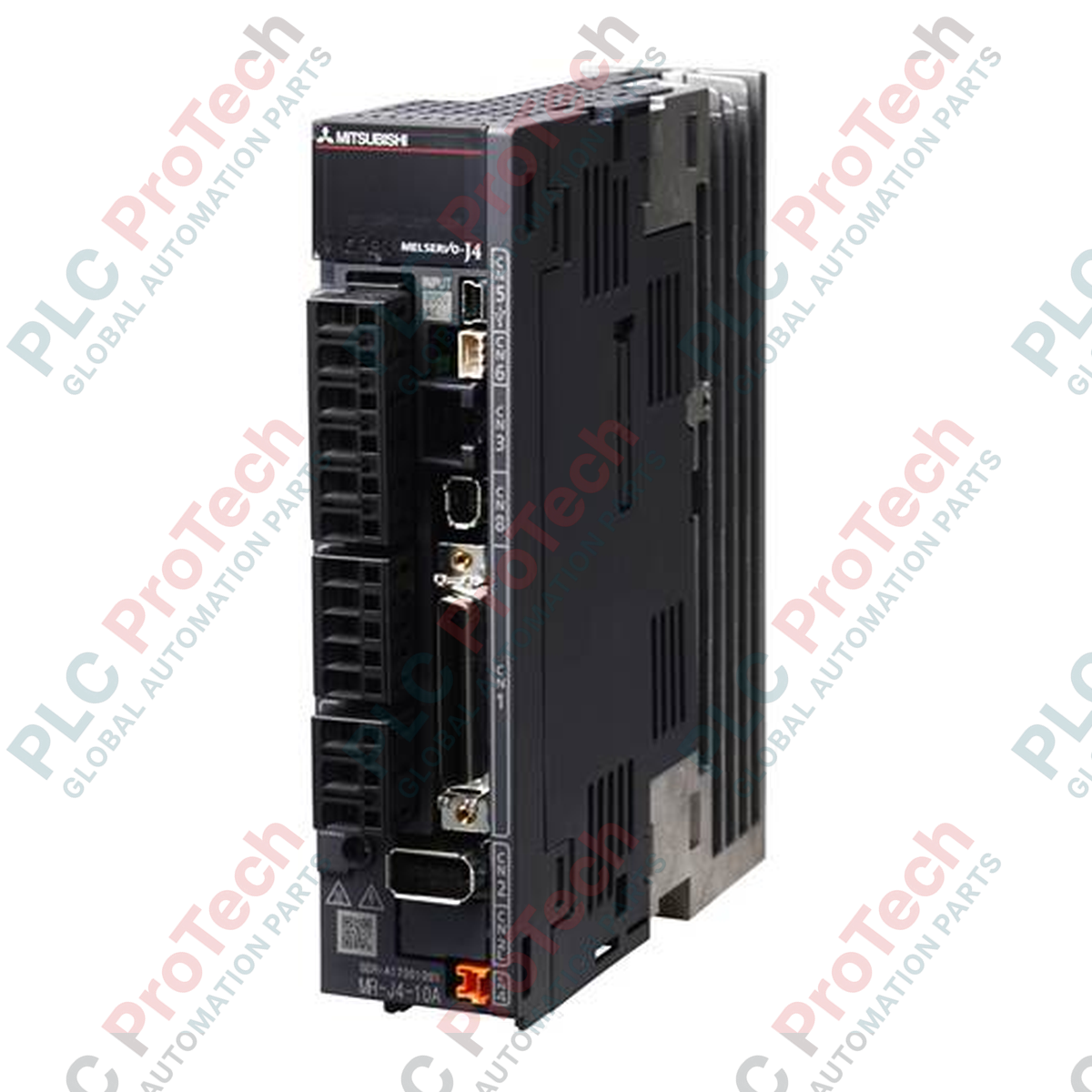
Operating on a 200V class supply, the Mitsubishi Electric MR-J4-10A single-axis servo drive is engineered to deliver highly responsive closed-loop motion control for 0.1 kW rotary, linear, and direct-drive motors within the MELSERVO-J4 automation platform. This unit interfaces seamlessly via a general-purpose command interface, accommodating both high-speed pulse train train positioning and analog speed or torque control methods. Equipped with 22-bit high-resolution encoder feedback, it achieves remarkable micro-positioning precision. Its robust diagnostic suite and integrated Safe Torque Off (STO) safety mechanisms ensure high reliability and compliance in demanding industrial system designs.
| Specification Parameter | Value / Rating |
|---|---|
| Manufacturer | Mitsubishi Electric |
| Model / SKU | MR-J4-10A |
| Series | MELSERVO-J4 |
| Output Rated Power | 0.1 kW (100 W) |
| Output Voltage / Current | Three-phase 170 V AC / 1.1 A |
| Main Circuit Supply Input | Single-phase or Three-phase 200 V AC to 240 V AC, 50/60 Hz |
| Allowable Input Voltage Fluctuation | 170 V AC to 264 V AC |
| Control Circuit Supply Input | Single-phase 200 V AC to 240 V AC, 50/60 Hz (0.2 A to 0.3 A) |
| Control System | Sinusoidal wave PWM control and current control system |
| Command Interface | General-purpose interface (Pulse Train, Analog, RS-422/RS-485, USB) |
| Safety Standard Compliance | EN ISO 13849-1 Category 3 PL e, IEC 61508 SIL 3, EN 62061 SIL CL 3 |
| Environmental Protection Rating | IP20 (Self-cooling / Open design) |
| Ambient Operating Temperature | 0 to 55 degC (no freezing) |
| Net Weight | 0.8 kg |
| Shipping Weight (Calculated) | 2.0 kg |
| Port / Connector | Function / Circuit Assignment |
|---|---|
| L1, L2, L3 | Main circuit power input (3-Phase AC 200V-240V). Connect to L1 and L2 for Single-Phase. |
| L11, L21 | Control circuit power supply input (Single-Phase AC 200V-240V). |
| U, V, W | Servo motor output terminals. |
| CN1 | Analog / pulse train command inputs and digital I/O signals. |
| CN2 | Encoder feedback interface connection. |
| CN3 | RS-422 / RS-485 serial communication port. |
| CN5 | USB port for MR Configurator2 configuration software. |
| CN8 | Safe Torque Off (STO) input signal interface. |
The MR-J4-10A features the standard general-purpose analog/pulse interface. It is a direct functional upgrade for legacy MR-J3-10A drives. However, configuration file parameter transfer must be performed via MR Configurator2 to map parameters accurately. Note that the MR-J4-10A is functionally and physically distinct from the MR-J4-10B, which operates exclusively on the high-speed fiber-optic SSCNET III/H network; they cannot be substituted for one another without swapping out the control network hardware.
When configuring the MR-J4-10A for single-phase operation, ensure that the power supply wiring is connected to the L1 and L2 terminals. If single-phase power is applied without adjusting the parameter settings to disable three-phase open phase monitoring, the amplifier will trigger an AL 10 (undervoltage) or AL 12 (memory error/phase open) alarm. Proper heat-dissipation clearance must be maintained when mounting adjacent to other units inside dense panels; a minimum distance of 10 mm on either side is recommended for optimal convection cooling.
To protect the high-resolution 22-bit absolute feedback signal from electromagnetic interference, always utilize double-shielded, twisted-pair cable for the CN2 encoder interface. Ensure the amplifier's ground terminal is bonded back to the primary electrical panel ground plate via a low-impedance connection. If feedback-line signal errors occur (such as AL 1A or AL 50), verify that the shielding connection at the motor-end connector has not been bypassed, and consider installing a high-performance power line filter on the main AC incoming power line.
CRITICAL WARNING
Risk of electric shock and residual energy hazard. Disconnect all main line power before installing, wiring, or servicing this equipment. Wait a minimum of 15 minutes after power-down to allow internal high-voltage capacitors to fully discharge before handling terminals.
Global Express Shipping
Returns & Warranty
Orders are processed and delivered Monday-Friday (excluding public holidays).
For full eligibility, restocking fees, and international return details, please view our official Refund & Return Policy .
| Country of origin |
United States
|

Implement a 3-SPST switch XOR light circuit in LogixPro or RSLogix 500 using an internal relay bit. Includes truth tables, boolean equations, and verified.

Integrate Allen-Bradley CompactLogix, Caterpillar ATS, and generators into DeltaV DCS over Modbus RTU. Covers ProSoft MVI69-MCM, Miille DIN266 gateways.

ONS instruction fires but the OTE coil never latches in Studio 5000 because the one-shot is only true for one scan. Use OTL/OTU or seal-in logic instead.

Configure Allen-Bradley Kinetix 5500 servo drives on EtherNet/IP. Covers CIP Sync, IEEE 1588 V2 timing, Stratix selection, DLR topology, and HMI.

A moving-average filter is the sliding-window smoother most instrument engineers drop into DCS and PLC analog paths. Here is how the window works, how N and sample time set lag, and when a...

On Frame 5–9 gas turbines, GE Mark VI and Mark VIe run control as function-block application software. This article maps process, protection, and sequencing functions—and what Toolbox ST access...