Description
Providing high-precision closed-loop motion control, the Mitsubishi Electric MR-J4-700B functions as a high-capacity servo drive designed for seamless integration within SSCNET III/H network architectures. Engineered for demanding industrial positioning applications, this unit pairs with 7.0 kW compatible rotary, linear, or direct-drive servo motors to deliver highly dynamic speed and torque response. Utilizing a high-resolution absolute encoder interface, the drive ensures exceptional trajectory tracking and minimal settling times, critical for multi-axis machinery coordinates.
Features
-
SSCNET III/H Interface: Utilizes high-speed fiber-optic communication running at 150 Mbps for synchronous multi-axis coordination and noise-immune signaling.
-
Advanced Vibration Suppression: Employs dual-frequency machine resonance suppression filters to minimize mechanical load oscillations.
-
High-Resolution Feedback Support: Integrates with 22-bit (4,194,304 pulses/rev) absolute encoders for superior positioning accuracy and velocity stability.
-
Integrated Functional Safety: Built-in Safe Torque Off (STO) compliance to meet international safety-standard requirements without redundant external hardware.
-
Real-time Auto-Tuning: Dynamically adjusts control loops to accommodate changing load inertia during physical cycle operations.
Applications
- Multi-axis CNC machine centers and gantry positioning units.
- Automated packaging, converting, and high-capacity winding machines.
- Heavy-duty Cartesian handling robots and material transfer lines.
- Semiconductor manufacturing and precision assembly systems.
Technical Specifications
| Parameter |
Specification Value |
| Manufacturer |
Mitsubishi Electric |
| Model Number |
MR-J4-700B |
| Series Name |
MELSERVO-J4 |
| Product Type |
Servo Amplifier |
| Control Communication |
SSCNET III/H (Fiber-optic) |
| Rated Capacity |
7.0 kW |
| Input Power Supply (Voltage/Phase) |
3-phase 200 V AC to 240 V AC, 50/60 Hz |
| Output Rated Voltage |
3-phase 170 V AC |
| Output Rated Current |
37.0 A |
| Cooling Method |
Forced cooling fan |
| Ambient Operating Temperature |
0 to 55 Celsius (non-freezing) |
| Net Weight |
6.2 kg |
| Shipping Weight (Calculated) |
8.0 kg |
| Country of Origin |
Japan |
Connections and Interfaces
| Terminal / Connector Name |
Description / Circuit Assignment |
| CN1A / CN1B |
SSCNET III/H fiber optic connection input/output lines |
| CN2 |
Encoder feedback connection interface |
| CN3 |
Digital I/O signals, limit switches, and manual pulse generator inputs |
| CN8 |
Functional safety STO input/output connector |
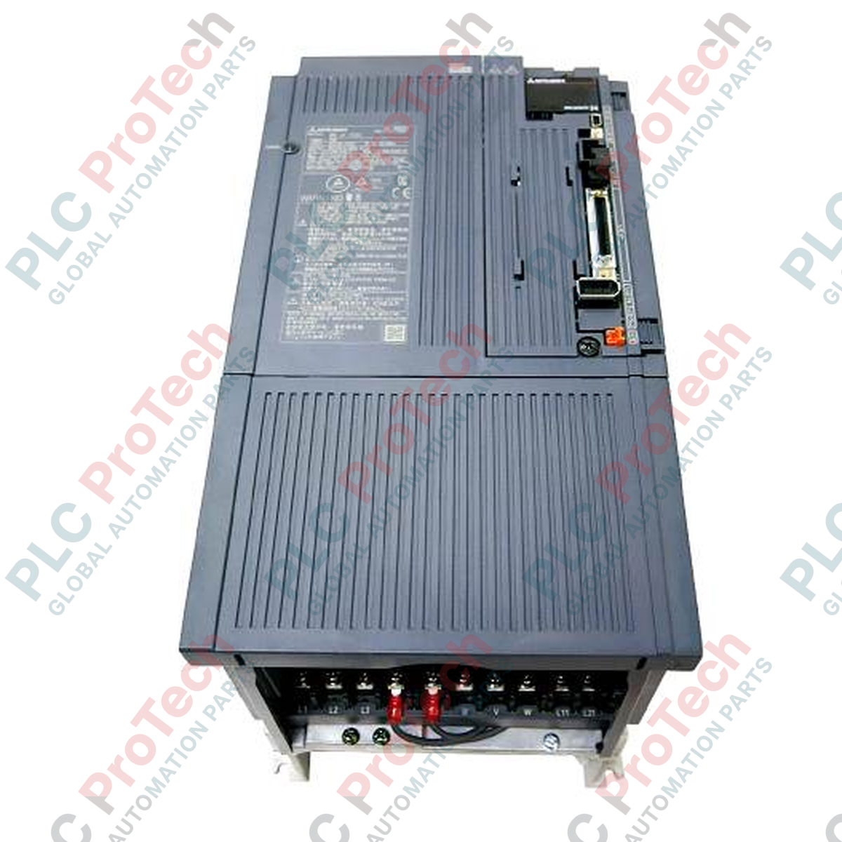
| L1, L2, L3 |
3-phase AC main power supply inputs |
| U, V, W |
Output terminals to motor phases (do not hook up to main power directly) |
Empirical Engineering Insights
Alternative Models & Compatibility
The MR-J4-700B is designed as a technological transition from the legacy MR-J3-700B. It can be set to run in MR-J3 compatibility mode via parameters using MR Configurator2. This permits easy drop-in mechanical replacement on older control system lines without immediately requiring a migration of the master motion controller or complete software overhaul. However, running in compatibility mode limits encoder feedback resolution to MR-J3 capabilities.
Application Pitfalls & Engineering Notes
Operating at a high power rating of 7.0 kW, this unit dissipates significant thermal energy. If housed in a completely sealed enclosure, maintain a minimum of 40 mm spacing on both sides of the amplifier housing to avoid localized hot-spots. If the ambient cabinet environment exceeds 40 Celsius, external cooling fans or air conditioners must be installed to prevent overtemperature thermal shutdown codes (AL.30 or AL.46).
Commissioning & Wiring Tips
The fiber-optic cables (MR-J3BUS_M) used on CN1A/CN1B require extreme handling care. They have a strict minimum bend radius of 25 mm. Exceeding this bend threshold will permanently fracture the optical core, triggering intermittent AL.37 (parameter communication error) or AL.E9 (main circuit warning) codes that are difficult to isolate during machine operation.
Installation Guidelines
CRITICAL SAFETY WARNING
Before starting installation or maintenance, completely disconnect all incoming AC power. Wait a minimum of 15 minutes for the internal high-voltage DC bus capacitors to discharge. Verify the voltage across terminals P+ and N- is under 20 V DC using a digital multimeter before touching wiring or terminals.
1
Vertical Panel Mounting: Mount the amplifier vertically on a metal control panel using the designated mounting holes. Securely tighten all bolts to maintain functional system grounding backplane continuity.
2
Power Wiring Routing: Terminate the 3-phase AC input to L1, L2, and L3. Connect the servo motor leads to U, V, and W. Ensure the green grounding terminal is connected back to the central plant PE grounding bus to eliminate ground loop noise.
3
SSCNET Optical Connections: Remove the dust caps from CN1A/CN1B ports. Align the optical connectors and insert firmly until an audible click is heard, ensuring the optical loop has optimal path transmission.
4
I/O and Safety Termination: Route shielding on all encoder and I/O signal wires with clamp blocks directly to the metal panel chassis. Run CN8 safety circuits through functional emergency stop channels before energizing power.