


Implementing 3-Switch XOR Ladder Logic with Internal Bit
Implement a 3-SPST switch XOR light circuit in LogixPro or RSLogix 500 using an internal relay bit. Includes truth tables, boolean equations, and verified.

Executing high-accuracy motion profiles within the MELSEC Q Series platform is direct and efficient with the Mitsubishi Electric QD75P2N. This dual-axis positioning module specializes in open collector pulse train outputs, providing seamless command control for stepper drives and servo systems. Designed for flexible architecture, it coordinates independent point-to-point (PTP) operations, continuous path trajectories, and multi-axis interpolation directly from the PLC backplane.
By housing dedicated processing hardware on-board, the QD75P2N offloads complex path calculations from the main CPU, ensuring consistent 1.5 ms startup response times. It supports multiple engineering unit systems, including millimeters, inches, degrees, and raw pulses, allowing engineers to program movement parameters directly in native machine units. The module stores up to 600 positioning data points per axis in non-volatile flash ROM, eliminating the requirement for external backup batteries.
| Specification Parameter | Value / Rating |
|---|---|
| Manufacturer | Mitsubishi Electric |
| Model Reference | QD75P2N |
| Series | MELSEC Q Series |
| Control Axes | 2 Axes |
| Output Interface Type | Open Collector Output |
| Maximum Pulse Frequency | 200 kpulse/s |
| Interpolation Modes | 2-axis linear, 2-axis circular |
| Internal Current Consumption (5V DC) | 0.30 A |
| Max. Drive Connection Distance | 2 meters |
| External Connection Port | 40-pin connector (compatible with A6CON1, A6CON2, A6CON4) |
| Occupied I/O Points | 32 Points (Intelligent function module) |
| Net Module Mass | 0.14 kg |
| Shipping Weight (Calculated) | 1.2 kg |
| Module Dimensions (H x W x D) | 98 mm x 27.4 mm x 90 mm |
The "N" suffix in the QD75P2N designates an updated hardware revision of the legacy QD75P2. Parameter structures remain highly backward-compatible; however, project validation within GX Works2 or GX Works3 is required to confirm configuration mapping. If your application demands longer transmission distances or higher pulse rates, consider the differential driver output version (QD75D2N), which extends pulse frequencies up to 4 Mpulse/s and connection runs up to 10 meters.
Because this module utilizes open collector outputs, the pulse signal quality degrades exponentially with cable length due to parasitic line capacitance. Standard installations must enforce the 2-meter physical limits between the module and the motor driver inputs. Exceeding this distance risks signal distortion, missed pulses, and erratic positioning errors. Additionally, ensure high-voltage motor cabling is separated by a minimum of 100 mm from the 40-pin command signal lines to prevent EMI-induced tracking errors.
The open collector output circuits within the module require an external DC power source to energize the optocouplers inside your servo/stepper drives. Verify that external 5V DC or 24V DC is supplied to the appropriate pin headers on the 40-pin connection layout. If the PLC diagnostics indicate active pulses are generating but the drive receives no commands, verify the presence of this external circuit voltage. We highly recommend using shielded, twisted-pair cables with the screen grounded exclusively on the PLC panel side.
CRITICAL SYSTEM SAFETY WARNING
Isolate all primary and auxiliary power supplies feeding the PLC rack, servo drives, and field machinery before mounting, removing, or wiring this module. Hazardous electrical arcs can damage internal CMOS components and lead to uncontrolled movement commands upon initial startup.
Align the module hook at the bottom of the QD75P2N onto the module mounting hole of the Q Series base unit, then press firmly into the slot until the top latch engages.
Secure the module to the base plate using the top-mounted retaining screw (M3 x 12). Tighten to a torque specification of 0.36 to 0.48 N-m.
Connect the pre-wired 40-pin connector (such as A6CON1 or A6CON2) to the front face of the module. Tighten the connector side-screws securely to prevent pin vibration during operation.
Global Express Shipping
Returns & Warranty


Manufacturer: Mitsubishi Electric
Product No.: QD75P2N
Country of origin:United States
Product Type: PLC Positioning Modules
Payment: T/T, Western Union
Weight: 1200g
Dimensions: 98 mm x 27.4 mm x 90 mm
Shipping port: Xiamen
Warranty: 12 months
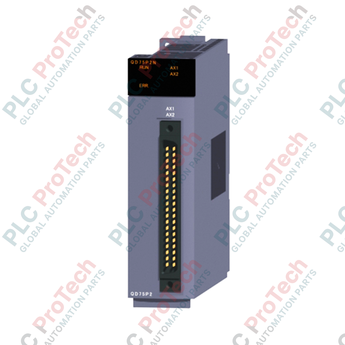
Executing high-accuracy motion profiles within the MELSEC Q Series platform is direct and efficient with the Mitsubishi Electric QD75P2N. This dual-axis positioning module specializes in open collector pulse train outputs, providing seamless command control for stepper drives and servo systems. Designed for flexible architecture, it coordinates independent point-to-point (PTP) operations, continuous path trajectories, and multi-axis interpolation directly from the PLC backplane.
By housing dedicated processing hardware on-board, the QD75P2N offloads complex path calculations from the main CPU, ensuring consistent 1.5 ms startup response times. It supports multiple engineering unit systems, including millimeters, inches, degrees, and raw pulses, allowing engineers to program movement parameters directly in native machine units. The module stores up to 600 positioning data points per axis in non-volatile flash ROM, eliminating the requirement for external backup batteries.
| Specification Parameter | Value / Rating |
|---|---|
| Manufacturer | Mitsubishi Electric |
| Model Reference | QD75P2N |
| Series | MELSEC Q Series |
| Control Axes | 2 Axes |
| Output Interface Type | Open Collector Output |
| Maximum Pulse Frequency | 200 kpulse/s |
| Interpolation Modes | 2-axis linear, 2-axis circular |
| Internal Current Consumption (5V DC) | 0.30 A |
| Max. Drive Connection Distance | 2 meters |
| External Connection Port | 40-pin connector (compatible with A6CON1, A6CON2, A6CON4) |
| Occupied I/O Points | 32 Points (Intelligent function module) |
| Net Module Mass | 0.14 kg |
| Shipping Weight (Calculated) | 1.2 kg |
| Module Dimensions (H x W x D) | 98 mm x 27.4 mm x 90 mm |
The "N" suffix in the QD75P2N designates an updated hardware revision of the legacy QD75P2. Parameter structures remain highly backward-compatible; however, project validation within GX Works2 or GX Works3 is required to confirm configuration mapping. If your application demands longer transmission distances or higher pulse rates, consider the differential driver output version (QD75D2N), which extends pulse frequencies up to 4 Mpulse/s and connection runs up to 10 meters.
Because this module utilizes open collector outputs, the pulse signal quality degrades exponentially with cable length due to parasitic line capacitance. Standard installations must enforce the 2-meter physical limits between the module and the motor driver inputs. Exceeding this distance risks signal distortion, missed pulses, and erratic positioning errors. Additionally, ensure high-voltage motor cabling is separated by a minimum of 100 mm from the 40-pin command signal lines to prevent EMI-induced tracking errors.
The open collector output circuits within the module require an external DC power source to energize the optocouplers inside your servo/stepper drives. Verify that external 5V DC or 24V DC is supplied to the appropriate pin headers on the 40-pin connection layout. If the PLC diagnostics indicate active pulses are generating but the drive receives no commands, verify the presence of this external circuit voltage. We highly recommend using shielded, twisted-pair cables with the screen grounded exclusively on the PLC panel side.
CRITICAL SYSTEM SAFETY WARNING
Isolate all primary and auxiliary power supplies feeding the PLC rack, servo drives, and field machinery before mounting, removing, or wiring this module. Hazardous electrical arcs can damage internal CMOS components and lead to uncontrolled movement commands upon initial startup.
Align the module hook at the bottom of the QD75P2N onto the module mounting hole of the Q Series base unit, then press firmly into the slot until the top latch engages.
Secure the module to the base plate using the top-mounted retaining screw (M3 x 12). Tighten to a torque specification of 0.36 to 0.48 N-m.
Connect the pre-wired 40-pin connector (such as A6CON1 or A6CON2) to the front face of the module. Tighten the connector side-screws securely to prevent pin vibration during operation.
Global Express Shipping
Returns & Warranty
Orders are processed and delivered Monday-Friday (excluding public holidays).
For full eligibility, restocking fees, and international return details, please view our official Refund & Return Policy .
| Country of origin |
United States
|

Implement a 3-SPST switch XOR light circuit in LogixPro or RSLogix 500 using an internal relay bit. Includes truth tables, boolean equations, and verified.

Integrate Allen-Bradley CompactLogix, Caterpillar ATS, and generators into DeltaV DCS over Modbus RTU. Covers ProSoft MVI69-MCM, Miille DIN266 gateways.

ONS instruction fires but the OTE coil never latches in Studio 5000 because the one-shot is only true for one scan. Use OTL/OTU or seal-in logic instead.

Configure Allen-Bradley Kinetix 5500 servo drives on EtherNet/IP. Covers CIP Sync, IEEE 1588 V2 timing, Stratix selection, DLR topology, and HMI.

A moving-average filter is the sliding-window smoother most instrument engineers drop into DCS and PLC analog paths. Here is how the window works, how N and sample time set lag, and when a...

On Frame 5–9 gas turbines, GE Mark VI and Mark VIe run control as function-block application software. This article maps process, protection, and sequencing functions—and what Toolbox ST access...