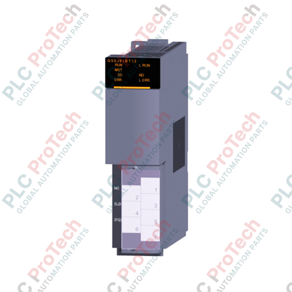
Description
Providing deterministic, functional safety communication across high-hazard environments, the Mitsubishi Electric QS0J61BT12 serves as a dedicated CC-Link Safety Master Station for MELSEC-QS control platforms. This safety master module coordinates safe remote I/O stations, executing rigorous diagnostics and safety-protocol verification over a standard physical bus topology. Engineered to integrate with Safety CPUs, it enables SIL3 and Category 4 compliant communication networks without requiring separate, dedicated wiring for safety and non-safety data signals.
Key Features
-
Selectable Baud Rates: Configurable transmission speeds ranging from 156 kbps up to 10 Mbps to match specific bus lengths and system cycle times.
-
High-Capacity Node Management: Connects up to 64 remote safety stations or general-purpose remote stations on a single network segment.
-
Dual-Layer Protocol Control: Employs independent CRC verification, using CRC32 for safe remote stations and CRC16 for general-purpose remote stations.
-
Flexible Topologies: Supports long-distance trunk lines up to 1200 meters at 156 kbps using standard Ver.1.10 compatible CC-Link dedicated cabling.
-
Intelligent Signal Processing: Allocates 32 points of intelligent I/O assignment per master slot directly to the safety controller backplane.
Industrial Applications
-
Automotive Assembly Lines: Distributed emergency stop circuits, light curtains, and interlocking gate switches.
-
Robotic Workcells: Coordinate safe-speed monitoring and perimeter guarding across multi-axis robot clusters.
-
Material Handling Systems: Conveyor safety integration, sorting line emergency systems, and heavy-payload lift stations.
-
Packaging Machinery: High-speed functional safety execution across multi-station indexing machines.
Technical Specifications
| Parameter |
Specification Value |
| Manufacturer |
Mitsubishi Electric |
| Model Reference |
QS0J61BT12 |
| Module Type |
CC-Link Safety System Master Unit |
| Station Type |
Safety Master Station |
| Supported Baud Rates |
156 kbps / 625 kbps / 2.5 Mbps / 5 Mbps / 10 Mbps (Selectable) |
| Max. Communication Distance |
1200 m (at 156 kbps) to 100 m (at 10 Mbps) |
| Max. Stations Connected |
64 Stations |
| Max. Link Points per System |
RX/RY: 2048 points; RWr: 256 points; RWw: 256 points |
| Communication Scheme |
Broadcast polling with frame synchronization |
| Line Coding |
NRZI Code |
| Physical Layer |
RS-485 Bus topology |
| Error Control (Safety Nodes) |
CRC32 standard algorithm |
| Error Control (Standard Nodes) |
CRC16 standard algorithm |
| Occupied I/O Points |
32 points (intelligent I/O assignment) |
| Internal Current Draw (5V DC) |
0.46 A |
| Net Unit Mass |
0.12 kg |
| Shipping Weight (Calculated) |
1.10 kg |
| Country of Origin |
Japan |
Connections and Interfaces
| Terminal Name |
Function & Signal Assignment |
| DA |
CC-Link Communication Line A |
| DB |
CC-Link Communication Line B |
| DG |
Signal Ground |
| SLD |
Shield Terminal (Internally tied to FG via capacitor/resistor network) |
| FG |
Functional Ground (Chassis ground) |
Alternative Models & Compatibility
This module is designed exclusively for mounting onto a MELSEC-QS Series physical backplane. It must operate alongside a QS001CPU Safety CPU module. While it functions on similar RS-485 physical hardware as standard Q-Series CC-Link modules (such as the QJ61BT11N), standard modules cannot be substituted for safety station master roles, as they lack the dual microcontrollers and CRC32 processing units necessary to run safety data frames.
Application Pitfalls & Engineering Notes
Ensure that all cable segments conform to the CC-Link Ver.1.10 physical layer standards. Mixing CC-Link cables from different generations or manufacturers within the same trunk line alters characteristic impedance, resulting in signal reflection. This reflection triggers transient CRC32 transmission errors, which force the host Safety CPU to transition into a "STOP" state to maintain functional safety protocols. Ensure termination resistors at each end match the cable's characteristic impedance (typically 110 ohms) exactly.
Commissioning & Wiring Tips
Always connect the shield (SLD) wire directly to the terminal block, and verify that the functional ground (FG) terminal is bonded to a low-impedance copper ground busbar in the panel. During software configuration in GX Developer or GX Works2, do not map safe I/O points to regular general-purpose I/O space; they must be mapped specifically via the "Safety Connection Parameter" tab to maintain strict software verification checks.
Installation Guidelines
CRITICAL WARNING: Ensure that the primary panel power source is completely de-energized and locked out (LOTO) before inserting or removing modules from the backplane. Failing to de-energize the rack can lead to internal backplane arc flashes, destroying the processor's ASIC, corrupting safety parameters, or causing unintended machinery movement.
1
Mounting: Hook the lower locating tab of the module into the base unit's guide hole and press firmly until the top lock-snap clicks.
2
Secure: Tighten the top module fixing screw (M3 x 12) to a torque of 0.36 to 0.48 N-m to ensure stable backplane connection and vibration resistance.
3
Wiring: Attach the prepared terminal block containing the CC-Link lines and the terminating resistor (if this is an end node) to the terminal block.
4
Grounding: Connect the FG terminal using a wire of at least 2 square mm cross-section directly to the central electrical ground point of the machine enclosure.