Description
Designed for direct integration into Sysmac PLC architectures, the Omron CJ1W-DA021 is a high-performance, dual-channel digital-to-analog conversion module. It enables precise control of external actuators, variable frequency drives, and process equipment by converting digital processor values into industry-standard analog signals. The module features robust photocoupler isolation between the internal controller CPU backplane and external field connections, shielding sensitive logic circuits from field-side electrical disturbances. With an integrated 18-point detachable terminal block, maintenance engineers can swap modules without disconnecting field wiring, minimizing operational downtime in continuous process environments.
Key Features
-
Dual Independent Output Channels: Supports independent configuration for both voltage and current outputs across two distinct field connections.
-
Multi-Range Flexibility: Software-selectable output signal ranges including 1 to 5 V, 0 to 5 V, 0 to 10 V, bipolar -10 to 10 V, and 4 to 20 mA.
-
Fail-Safe Output Hold Function: Configurable recovery behavior (CLR, HOLD, or MAX) to preserve, clear, or maximize output signal states if the controller CPU encounters an error or stops executing.
-
High Resolution: Operates at an industrial-grade conversion resolution of 4,000 (1/4000) for smooth ramp profiles and precise valve positioning.
-
Detachable Terminal block: 18-point M3 screw terminal layout simplifies cabinet pre-wiring and field module swaps.
Applications
- Speed referencing for Variable Frequency Drives (VFDs) and servo controller velocity loops.
- Positioning and flow adjustment for pneumatic and hydraulic proportional control valves.
- Set-point configuration feed to discrete temperature controller units and recording devices.
- Simulating transducer signals during commissioning of remote supervisory control systems.
Technical Specifications
| Specification Parameter |
Value / Detail |
| Manufacturer |
Omron |
| Model Number |
CJ1W-DA021 |
| Module Type |
Analog Output Unit |
| Number of Outputs |
2 channels |
| Analog Signal Formats |
1 to 5 V, 0 to 5 V, 0 to 10 V, -10 to 10 V, 4 to 20 mA |
| D/A Conversion Resolution |
4,000 (16-bit binary data representation) |
| Conversion Speed |
1.0 ms per point |
| Accuracy (at 25 degC) |
Voltage: +/-0.3% of F.S. | Current: +/-0.5% of F.S. |
| Accuracy (0 to 55 degC) |
Voltage: +/-0.5% of F.S. | Current: +/-0.8% of F.S. |
| Isolation Mechanism |
Photocoupler isolation between controller backplane and outputs; no isolation between channels |
| External Power Supply |
24 VDC (+10% / -15%), 140 mA max (Inrush: 20 A max, pulse width 1 ms min) |
| Internal Power Consumption |
5 VDC, 120 mA max |
| Output Impedance (Voltage) |
0.5 Ohms max |
| Max Load Resistance (Current) |
600 Ohms max |
| Country of Origin |
Japan |
| Shipping Weight (Calculated) |
0.35 kg |
| Package Dimensions (Calculated) |
11.5 cm x 10.5 cm x 4.5 cm |
Connections and Interfaces
The module interface uses an 18-point detachable terminal block setup. Terminal assignments must align strictly with the target signal type to prevent internal component fatigue.
| Terminal Connection |
Signal Allocation / Function |
| A1 / B1 |
External Power Supply Input (+24 VDC / 0 V Ground) |
| A3 / A4 |
Channel 1 Voltage Output (+) / Output Common (-) |
| A5 / A4 |
Channel 1 Current Output (+) / Output Common (-) |
| B3 / B4 |
Channel 2 Voltage Output (+) / Output Common (-) |
| B5 / B4 |
Channel 2 Current Output (+) / Output Common (-) |
Empirical Engineering Insights
Alternative Models & Compatibility
The CJ1W-DA021 shares form-factor and configuration parameters with standard CJ1, CJ2, and NJ controller backplanes (when utilized with an EtherCAT or EtherNet/IP bus coupler). It serves as a direct drop-in replacement for legacy CJ1W analog variants. However, verify the CPU allocated memory map registers (CIO area), as older program structures might require address validation depending on the unit number assigned via the front-panel rotary switch.
Application Pitfalls & Engineering Notes
Note that there is no electrical isolation between Channel 1 and Channel 2 outputs on this unit; both share a common ground reference (Output Common). If connecting to two field instruments with differing ground references, ground loop currents can corrupt analog signals or damage the output stage. Ensure field instruments have isolated inputs or use external signal isolators to maintain loop integrity.
Commissioning & Wiring Tips
To mitigate electromagnetic interference in high-noise environments (such as proximity to active VFD switchgear), always use shielded twisted-pair (STP) cabling for the analog loops. Ground the cable shield strictly at the PLC enclosure ground panel and leave the instrument end ungrounded to prevent ground loops. Never route analog output cables inside the same wire duct as high-voltage AC power lines.
Installation Guidelines
CRITICAL WARNING: Ensure all power to the PLC rack and the external 24 VDC field supply is completely disconnected before mounting, unmounting, or wiring the module. Hot-swapping the module can cause latch-up conditions or permanent damage to the CPU backplane logic.
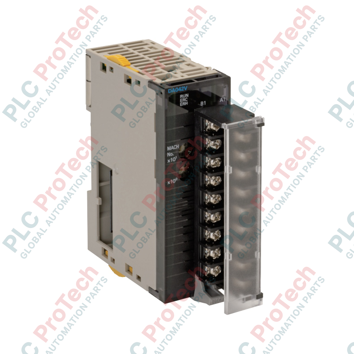
1
Set the Unit Number rotary switch on the front panel of the CJ1W-DA021 using a small flathead screwdriver. This allocation must match the hardware configuration in CX-Programmer or Sysmac Studio.
2
Mount the module onto the CJ-series backplane, aligning the bottom hook and snapping the top locking mechanism firmly into place. Secure the yellow slide locks to ensure mechanical stability.
3
Wire the external 24 VDC power supply to terminals A1 (+) and B1 (-) to energize the conversion circuitry, then wire the analog load loops according to the designated voltage or current terminals.